TPA3116D2 Boards
Introduction
These have become very popular now and seem to have become the "new tripath ta2020 etc". Already in less than one year since the first non evaluation module emerged onto the market are many boards to choose from that utilize this IC. Threads are heavily polluted so this can be a place for people to document facts, tutorials etc with out the discussion pollution.
Given that some are calling the TI tpa311x series the "new tripath", some of the general information in the Sure TK2015 Modification wiki might be relevant.
There are other IC's in this family, but to date this is by far the most popular. With the TPA3110 sure electronics boards also being popular given their sub $10 dollar price tag.
Texas Instruments' TPA3116 Datasheet: https://www.ti.com/lit/ds/symlink/tpa3116d2.pdf
Massive diyAudio thread on this amp: TPA3116D2 Amp.
Available Boards
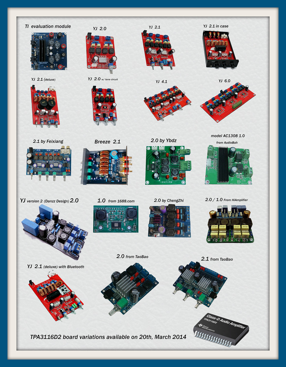
There are many pre-made TPA3116 PCBs available. diyAudio member KJA 2013 was keeping track of them. Latest picture with all known boards from post #2249:
Power Supply
Per the TI tpa3116 datasheet, the acceptable voltage range is 4.5 to 26 Volts. People have reported success across most of that range. Popular power supply voltages include 12V, 13.8V, 19V, 24V. Power supply can be any type: linear, switch mode or even battery. There were some reports that the sweet spot is obtained by staying under 21 V. 19V switch-mode power supplies are common for laptop computers (and some computer monitors); they are cheap and readily available.
A few members have reported great success with high-current regulated linear power supplies designed for HAM radio. In particular, the Astron RS-12A and Ten Tec 937 (which appears to be a re-branded Astron SL-11A).
Regarding batteries: sealed lead acid (SLA) and lithium iron phosphate (LiFePO4) are good choices.
How Much Power Do I Need?
Page 10 of the datasheet has useful graphs for computing max power needed.
Using the upper-right graph, maximum output power at 4ohm load, 26dB gain, BTL mode for 14V power supply is about 25 watts (and that's at 10% THD, unlikely anyone would ever want to listen at that level). Multiply by two for two channels, so say 50 watts total output power.
Using the graph just below that, the efficiency should be around 85%, but let's call it 80% just to be conservative.
50/.8 = 62.5 Watts of input power. For a 14V power supply, that works out to about 4.5 Amps. (Cut that in half if using 8 ohm speakers.)
The above calculation errs on the conservative side (i.e. some headroom is built-in to the calculations). However, you can always have a power supply that makes more current (Amps) available; the amp will only draw what it needs. (But voltage must be kept within the 4.5V to 26V range.)
The above example calculation can be used as a template for calculating required current at different voltage levels.
Note that the graphs on page 10 of the datasheet are for BTL mode. For PBTL mode, see the graphs farther down, on page 12.
Power On/Off Pop
Quote:
| A switch between pin2 SDZ and gnd seems easiest way to avoid any pop, it puts the tpa3116chip in standby/off position. There are some boards doing that, those are even more quiet then the mute pin controlled on/off. Then there are boards doing both, I think the purple heatsink without remote does for example, the remote/display version just uses SDZ and is completely quiet, not a little crack, never... |
CyberPit's Circuits
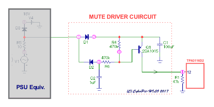
A BJT-based one:
This circuit is diverted the audio-line pop noise muting transistor driver circuit. (Of course, You can use this for its intended purpose)
https://cyberpithilo.web.fc2.com/aud...ng_circuit.png
It is verbosely explained at his website (use a web translation service if you don't read Japanese).
Source: #10456 / CyperPit
The same circuit, just differently drawn:
Source: #10472 / CyperPit
Note that this schematic misses a series resistor between the output(Collector) and the TPA3116D2's mute pin - without it, the mute pin can be pulled-up 20mA max. way above TPA3116D2's PVCC at power-off, which may damage the chip inside clamp diode . Assuming a 100k pull-down on the mute pin, the output series resistor can be 100k, too - this ensures a very small current, yet sufficient voltage. If you feel too sensitive to the voltage drops, you can add some series of diodes at the most left diode D?
And a FET-based circuit:
Source: CyperPit (some explanations in subsequent posts)
Note: A SMD package 2N7002 is also available instead of 2N7000. Diode D should not use a Schottky, because reverse leakage current makes error on a power-up muting duration.
CyberPit recommends FET version rather than BJT-based one.
The Giancarlo Circuit
See the discussion on the TI E2E Community "TPA3130D2 SDZ & MUTE".
Circuit:
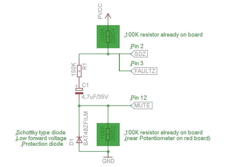
Additional explanation from post #3528 by Giancarlo69 24th June 2014:
Note that this circuit does not suppress a possible power-off pop.
Circuit:
Additional explanation from post #3528 by Giancarlo69 24th June 2014:
Quote:
|
From datasheet: "The gain setting is latched during power-up and cannot be changed while device is powered" The above circuit does not interfere with the proper operation of the amplifier. Anyway SDZ is always deactivated, because is at high logic level and only MUTE pin is active for for a short time after power-on. The delay depends by C1 value, power supply voltage and only minimally by R1. With 21V of power supply and values in the schematic, the delay is about 1.8 seconds. Doubling C1 will double the delay. The lower the value of power supply, the lower the delay time. Without R1 (0 ohm ) the delay will be about 1.5 seconds. So, why have I added R1? 'cause in case of fault condition, like for example overtemperature,"FAULTZ" pin, that is connected to "SDZ" pin, goes to low logic level and R1 will limit C1 discharge current. In such a case, without R1, there would be a very high spike of current on "FAULTZ" & "SDZ" pins. About D1: Probably I'm overly cautious strictly indicating the use of a schottky diode for D1, but this is only for a safety reason, 'cause in the datasheet has been indicated an absolute limit of only -0.3V for "MUTE" pin. With a Schottky diode, the voltage on mute pin will be -0.25V, and so within that limit. With a regular (silicon) diode, the voltage on mute pin will be about -0.5...-0.6V, that is above the limit. I dunno if a brief voltage of -0.6V could be damage the chip on long term, very probably not, but it cannot be guaranteed 100% |
Yuan-Jing Blue/Black 2.0 Board - Danzz Design
There are many implementations of this board, but the one offered by Yuan-Jing ("YJ") has become one of the most popular. It appears to be based of the design by diyaudio member danzz.
- Yuan-Jing Link
- This board now appears to be available from multiple sellers on ebay.
- Danzz post #941. This contains danzz's PCB schamatic on which the YJ board is based.
- danzz re-posted in #1469
- KJA 2013 post #1476 posted nice color pics of the YJ board.
- Yuan-Jing also offers a completely assembled amp based on this board.
Yuan-Jing (YJ) Blue/Black 2.0 Board - Popular Modifications
Most of the components on the YJ Blue/Black board are through-hole and relatively easy to change.
Here's a labeled picture of the YJ blue/black board:
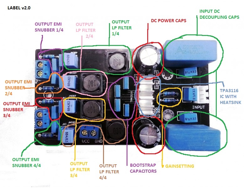
Here's a labeled picture of the YJ blue/black board:
DC Power Caps
Datasheet suggested value: 220uF
Notes on DC Power Capacitors:
- Current group favorite as of August, 2014 appears to be the Panasonic "OSCON" caps. In particular, Panasonic part number 25SEPF330M, Mouser part number: 667-25SEPF330M, DigiKey part number: P16323-ND
- 330uf 25v Panasonic hybrid electrolytics EEH-ZC1E331P. Mouser 667-EEH-ZC1E331P. "Nice bonus is the leads fold down so that they can be used as SMDs or regular through-hole. Clever."; Source: audiocircle #658 / wushuliu
- Panasonic EEH-ZA1V271P CAP ALUM 270UF 35V 20% SMD. Digikey P15453CT-ND. "Pricey but you asked for the best [in tpa3110 context]."; Source: #1293 / Saturnus
- 470uF / 35V Panasonic FM caps; Source: audiocircle #609 / rhing
- 2,200uF / 25V Panasonic FM; Source audiocircle #609 / rhing
Notes on DC Power Capacitors:
- Recent discussion suggests larger values may be sub-optimal.
- Source: audiocircle #629 / rhingQuote:
I took out the 1,000uF / 25V Elna Silmic II caps on my Sure Electronics TPA3110 amp and replaced them with a pair of 470uF / 35V Panasonic FM caps. I left the single 2,200uF / 25V Panasonic FM on the power supply inputs. The amp sounds smoother, more relaxed and better tonally. On some music like classical with heavy strings, the treble used to almost squeal at higher volumes. It was also a little smeared. Now it's very clean, and there is also less hiss/noise. At $10 a board plus about $15.00 of electrolytic caps and Bourns Ferrite beads as output filters, this amp is a real bargain. - Source: #2896 / rhingQuote:
I've been re-thinking the use of 1,000uF and greater capacitance on the DC decoupling caps in my TPA3116 and TPA3110 amps. The ChengZhi amp had a pair of stock 470uF/25V Sanyo OSCON-clone caps and the amp sounded smoother than either of my amps. I decided to swap in a pair of Panasonic FM 470uF/35V caps into my Yuan Jing TPA3110 blue amp (Danzz's design), and I found the amp to sound smoother and more musical. The tonality improved and the amp just sounded more relaxed and more fun to listen to. I then did the same change with my Sure Electronics TPA3110 amp, and I got the same improvements. In both amps, I have a Panasonic FM 2,200uF/25V on the power supply input on the board. I did the same with the ChengZhi amp too, and I have to say the bass response is more impressive with the smaller caps close to the amp IC and the larger cap at the power supply input.
Input Signal DC De-coupling Caps
Stock YJ Blue/Black: Epcos MKP X2
- 1.0uF / 250V Wima MKP10 metallized Polypropylene. Mouser 505-M101.0/250/5; Source: #2303, #2312 / rhing
- Panasonic ECQ-E1106KF - metalized polyester, 10 uF 100V, 10%; "FYI, I've found going from 1uf to 5-10uf for input cap brings out much more bass."; Source: #423 / wushuliu
- Dayton MKP 2.2uf input caps, Jantzen Superior 2.2uf input caps; Source: audiocircle #658 / wushuliu
- WIMA MKS4 4.7uF (big ones) and WIMA MKS2 4.7uF (little ones); Source: #2864 / steveeboy
Bootstrap Capacitors
- TDK FK20X7R2E224K .22uf 250v X7R caps. Mouser 810-FK20X7R2E224K, Digikey 445-2645-ND; Source: audiocircle #658 / wushuliu
Notes on Bootstrap Capacitors:
- Source: #1240 / SaturnusQuote:
If I were to pin point a single element that by changing it could improve the vast majority of chip based class D amps, it would be the bootstrap capacitor as it's often forgotten that the output signal runs directly through it as part of the commutation current cycle of every single half cycle.
Often this is too far from the chip as maximum recommended distance is usually 5mm or less, often the value is downsized, the quality and type not considered with care, I could go on.
It should be a ceramic X7R capacitor of 10 times (or at the very minimum 4 times) the voltage rating of the amplifier to ensure frequency stability and lowest possible noise. Or alternatively a niobium oxide of 2 times the voltage rating of the amplifier for same.
Volume Pot
- Panasonic EVJ 50k pot. Digikey P2G1503-ND; Source: #2303, #2312 / rhing
Gain Setting
Factory default gain setting on the YJ blue/black board is 26 dB.
Source: tpa3116 datasheet, Table 1. GAIN and MASTER/SLAVE (page 15)
Note: in the TI datasheet (and in the table above), the gain setting resistors are referred to as R1 and R2. On the Danzz-design YJ blue/black board, the gain setting resistors are labeled R12 and R13.
Code:
MASTER/SLAVE   GAIN    R1 (to GND)   R2 (to GVDD)   INPUT IMPEDANCE
Master         20 dB   5.6 kOhm      OPEN           60 kOhm
Master         26 dB   20 kOhm       100 kOhm       30 kOhm
Master         32 dB   39 kOhm       100 kOhm       15 kOhm
Master         36 dB   47 kOhm       75 kOhm        9 kOhm
Slave          20 dB   51 kOhm       51 kOhm        60 kOhm
Slave          26 dB   75 kOhm       47 kOhm        30 kOhm
Slave          32 dB   100 kOhm      39 kOhm        15 kOhm
Slave          36 dB   100 kOhm      16 kOhm        9 kOhm

* Resistor tolerance should be 5% or better
Note: in the TI datasheet (and in the table above), the gain setting resistors are referred to as R1 and R2. On the Danzz-design YJ blue/black board, the gain setting resistors are labeled R12 and R13.
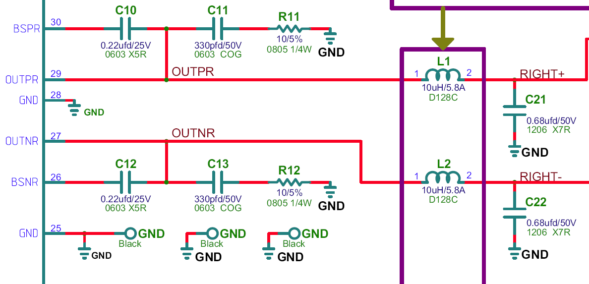
Output Filter Capacitors
- Wima FKP, MKP, and MKS for .68uf, 10nf, and 1nf output filter caps; Source: audiocircle #658 / wushuliu
Output Filter Inductors
- Bourns 10uH toroid inductors. Mouser 652-2100HT-100-V-RC, Digikey 2100HT-100-V-RC-ND; Datasheet: https://www.mouser.com/ds/2/54/2100ht_series-8038.pdf; Sources: #327 / KJA 2013#2303, #2312 / rhing
- Coilcraft SER2915L 10uh inductors; Datasheet: https://www.mouser.com/ds/2/597/ser2900-270685.pdf; Source: audiocircle #658 / wushuliu
- Coilcraft RFS1412-103ME (10uH for 4 ohm), RFS1412-223KE (22uH for 8 ohm); https://www.coilcraft.com/pdfs/rfs1412.pdf; "For those wanting to retrofit inductors neatly onto their existing board, the CC RFS1412 range looks ideal (144mm dia, 12mm high). A bit higher DCR but still probably more than adequate."; Source: #2770, #2776 / abraxalito
- Coilcraft MSS1210-103MED; Source: #694 / Virpz
- ICE 10uH 1D14A-100M. Mouser 911-1D14A-100M; Source: #327 / KJA 2013
- Wurth 7443631000; Datasheet: https://katalog.we-online.de/pbs/dat...7443631000.pdf; Sources: #673, #694 / Virpz; #2752 / DUG
- Wurth 7443321000. Mouser 710-7443321000, Digikey 732-2145-6-ND; Source: #673, #694 / Virpz
- Wurth 7447709100; Datasheet: https://katalog.we-online.de/pbs/dat...7447709100.pdf; Sources: #2515 / BL21DE3; #2752 / DUG
- Wurth 74437349100; Datasheet: https://katalog.we-online.de/pbs/dat...4437349100.pdf; Source: #2752 / DUG
Notes on Ouput Filter Inductors:
- Each of the four inductors corresponds to one side of the output filter. That is, one inductor for each of right+, right-, left+, left-. The inductors, along with the three capacitors and one resistor, are part of a low-pass filter which removes high-frequency noise created by the tpa3116's switching.
- Relevant article: Understanding output filters for Class-D amplifiers | EE Times
- Related diyAudio discussion: Match Your Output Filter to Your Speakers - All Boards Welcome
- Another relevant article: Class D Audio Amplifiers: What, Why, and How By Eric Gaalaas
- RLC Low-Pass Filter Design Tool
- Source: audiokarma #264 / rhingQuote:
The LC output filter on the blue amp is optimal for an 8 ohm load. If you look at the red amp, the LC filter is really optimal for a 4 ohm load (22uH inductors on red vs. 10uH inductors on blue). - Source: #232 / SaturnusQuote:
The roughly 3dB peak at 16khz (slowly rising from roughly 2khz) using a 22mH output inductor will cause can be beneficial to some full-range speakers or tweeters that have a declining output, btw. It's also followed by a higher Q at peak, so expect some extra added sparkle in the highest treble. - Source: #236 / xrk971Quote:
The thing to look for in inductor specs is whether or not the specified nominal inductance value stays constant as a function of current. The cheaper ones will have a reduced inductance as current goes up. The other thing to look for is what the current rating is. For 40 watts driven by 17 volts the peak current is 2.35 amps. This level of current is really only for peaks and transients as we will operate below 25 w most of the time in a continuous mode. Many of the inductors should be rated for at least 2 amps and ideally 3 amps. I know Dug has looked into this extensively and can provide us more tips. You have to look at the manufacturers spec sheets for performance vs current. - Source: #2741, 2746 / abraxalitoQuote:
There's art in choosing the optimum core material. I think that inductors sound different due to different losses. Ferrite is lowest loss but the normally fitted ferrites are rather undersized and made from very cheap core material (too high losses). When I eventually get one of these amps to try I'll experiment with hand-wound ferrite cores made from quality material with relatively large gaps to ensure no saturation.
Flux we want contained, hence a magnetically shielded inductor is called for. Losses come in two forms - copper and core. An air cored inductor uses more wire than any other kind so has more copper losses than others, but has zero core loss (because the core is just air).
Copper losses are fairly complex to estimate for an inductor at high frequencies (such as here) because skin and proximity effects (causing the current to concentrate in a narrow band at the surface of a wire) need numerical methods to quantify them.
Helpful Hints on Stock Inductor Removal:
- Source: audiocircle #402 / rhingQuote:
Removing the inductors was a bit tricky without ripping the surface mount pads from the amp board. I thought I could just heat the solder joints simultaneously with two solder irons and the inductors would fall off. However, the solder that Yuan Jing uses hardly reflows. I had to use a toothpick to apply some gel flux paste to the solder joints and heat the joints with my solder iron while very gently lifting the stock inductors off the board. I was able to neatly remove them all and keep the surface mount pads in place. - Source: #2311 / Destroyer OSQuote:
Another trick is to just put a dab of solder (good solder, I use Kester 44) on each soldering iron tip then reach in there. You know, for when you don't have anything else. In fact I often add a little solder to chinese and other lead free or otherwise crappy solder, as it allows it to flow and suck up much nicer. A little more solder sucks better than a little less, too. - Source: #2889 / DUGQuote:
My method:
Use a sharp bladed knife to put slight upward pressure on the inductor and heat each side alternately.
Do not rush.
After 30 seconds (or if you feel the board getting too hot) stop and let everything cool for a few minutes...then resume.
A note for heat-up Inductor on XH-M139 Amplifier:
This model uses very poor yellow toroidal-core inductors. Once saturated with high-current output. The inductance will lost, then the temperature goes quite high enough to burn. De-magnetize core or change to Hi-current (Metal -Alloy) type inductor is the only way to solve this problem.

Bootstrap Snubber Mod
In post #3823 on 13th July 2014, xrk971 described a successful bootstrap snubber mod. Here is the snubber schematic:
And here is a pic of xrk971's work:
See the post for more information.
Later, in post #3845 on 14th July 2014, skylab posted another picture of a successful mod:
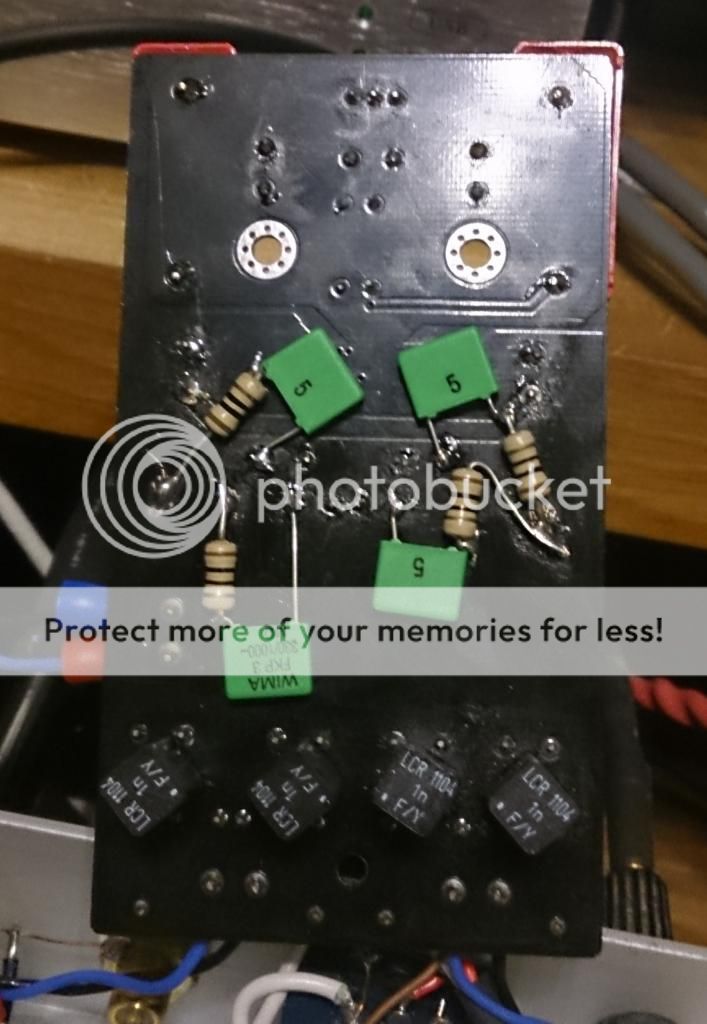
Another note: thin film resistors may be preferred for this mod.
Source: #4658 / xrk971
And here is a pic of xrk971's work:
See the post for more information.
Later, in post #3845 on 14th July 2014, skylab posted another picture of a successful mod:
Another note: thin film resistors may be preferred for this mod.
Quote:
| ...Wire wound resistors will change inductance of main filter. I use thin film resistors... |
This page has been seen 49,405 times.
-
-
Created by onLast updated by on
-
- Contributors: