Hey Girls and Guys!

Hello Folks!

I am a general DIY guy, being an EE as profession.
I hope to get some insigths from more experienced folks over here for a new portable Speaker project of mine.

I am not a complete beginner and designed a few BR housings back in the day. (Just look at my registration date, i never got to posting here 😉 )

However i really need to lern a lot.

microphonicity with cathode positive w/respect to heater

Hi all,
after years of Big Talk I finally built the guitar amp I'd been thinking about for years. Still needs a few tweaks, but it's already gig-able and working/sounding really sweet.
Here's the question: I notice to my surprise that the tube which seem most sensitive to direct physical disturbance is not the (very very) high gain input pentode nor one of the other gain-providing stages, but the one hosting the cathodyne phase splitter and another near-unity stage with the same equal plate and cathode loads. I am gathering that what makes these more microphonic is the fact that the idle cathode voltage is elevated from that of the heaters - I read this somewhere, at any rate. It's a 6SN7 and the cathodes are at roughly 85V so I'm nowhere near the limit on the datasheets (200V positive) even with maximum possible signal going through there.
I am not experiencing a particular problem - I can set the head on top of my speaker, and if it's picking up something extra microphonically, I can't necessarily hear it. If you tap that tube directly (I know I know, "don't do that") it's pretty loud. Even before you tap it you can hear the heater hum increase when your hand gets near to it.
Here's the question for real: Is there any trick for quieting it down I should know? I'd just feel better about my creation if it didn't act like this.

Installing and using LTspice IV (now including LTXVII), From beginner to advanced

INDEX

Recent months have seen Linear Technology become absorbed into Analog Devices. The good news is that LTIV remains available (although unsupported) for legacy systems running older operating systems.

The successor to LTIV is LTXVII which is under constant development, just as LTIV used to be. Both these simulators are now hosted on the Analog Devices site.

Users just starting out with LTspice and running modern hardware should consider using LTXVII over the older unsupported version. Much of what is written here is applicable although subtle differences in operation will become apparent as you dig deeper.


1/ Installation. Post #1 (you are here)

2/ Running a simple DC simulation. Post #2 and #3 HERE

3/ Running a simple AC simulation. Post #7 HERE

4/ Simulating a one transistor Amplifier. Post #14 and 16. HERE

5/ Distortion and FFT's. Post #19 and 20 HERE

6/ Squarewave Testing. Post #31 Here

7/ Measuring AC voltages. Post #35 Here


8/ Setting up multiple signal sources and running two simulations in parallel. Post #39 Here

9/ Adding ripple to the PSU. Post #51 Here

10/ Simulating a simple PSU. Post #59 Here

11/ Adding and simulating a voltage doubler and regulator. Post #67 Here

12/ Testing under load and dynamically. Post #71 Here

13/ Adding models to use in a simulation. Post #85 Here

14/ Adding a PSpice 3rd party model to a simulation. Post #146 Here


15/ Measuring amplifier output impedance. Post #214 Here

16/ Stepping a component value. Post #222 Here

17/ Stepping the bias of an amplifier. Post #225 Here

18/ Adding your own Subcircuit Model to LTXV11. Post #2272 Here


Subsection... Ideas and Tutorials submitted by diyAudio members

A/ Using LTSpice simulation command for a DC sweep for resistors. For a worked example see post # 560 Here

(submitted by pr)

B/ Functional LF198/LF298/LF398 Sample and Hold, post #754 here (submitted by FdW)

C/ Limit the length of figures to a set length independent of the exponent while at the same time rounding the number,
post #1915 Here
(submitted by FdW)

D/ A gyrator calculator in LTSpice for graphic EQ design. Thread is Here (submitted by Cabiro)


*********************************************************************************************

The purpose of this thread is to show how to both install and to use LTspice, hereafter just referred to as LT, the free circuit simulation program from Linear Technology (now Analog.com). I consider myself very much at the beginner end of the spectrum, but I'm hoping that as the thread develops we can gather input from those more seasoned users amongst you all...

A picture... or two or three... are worth a thousand words.

Can you believe it took me many days to figure out how to include a simple model for a device into a simulation. For a newbie it needs to be a click by click instruction with pictures.

Credits... firstly to Bob Cordell and his excellent book "Audio Power Amplifiers". I can say with certainty that I would still be staring at the blank grey workspace of LT had it not been for Bobs excellent introduction to this fantastic program. I would urge anyone with an interest in simulating amplifiers to "go buy the book". You won't regret it.

Thanks also to Keantoken who has a prety comprehensive WIKI on the site. Take a wander over when you've a few minutes spare and have a read.


So lets get started.

LT is best downloaded from Analog.com Be sure to download LT IV (for the purposes of this tutorial), or you may wish to install both versions (LT IV and LTXVII) and retain LT IV as a legacy program.


Old URL which currently redirects correctly to Analog Devices.
Linear Technology - Design Simulation and Device Models

Direct Analog.com URL
LTspice from Analog.com

The version marked for Windows XP is LTIV. All other options are for LTXVII. There is also a Windows and Mac version with this thread being based on the Windows version.

Install LT as you would any other program. On Windows the installer will probably say you have UAC (user account control) enabled and that it may cause issues with file paths. I have used LT on Vista, W7 and W8.1 with no unresolvable issues by leaving UAC on.

When you have installed LT you should find you have a desktop icon to open it... the usual stuff. What you should now is change the icon (or whatever means you yourself use to open programs) to run as administrator. This is important because LT will not run and update correctly if this is not done.

To do this, right click the icon and using the <properties> tab, change the shortcut to "Run as administrator". This picture show it for Windows 8.1, W7 and Vista are similar.


Next thing we do is open LT and set a few basic options. Setting these options as shown ensures that LT doesn't accumulate a lot of temporary files... even then its not foolproof... we'll cover that later.


Nearly there, but first lets get to know where LT lives on your PC and how it handles files and folders. This is important in order to keep your system tidy and to make it easy to keep track of things.

Depending on your operating system, go to the run box and type C:\Program Files.


You should see something like this with LTC being the folder of interest. Click your way through the folder to open it. You will see this.


The <scad3> line is the program shortcut. If you are using W8.1 then this is probably the best place to alter the settings mentioned above to "run as admin". There is a folder of examples in there too, as well as all the models and files LT needs to run.

I recommend that you DONT add to, or change anything in those folders at this stage.

Lets just jump ahead of ourselves at this point because there is something worth mentioning. If you run a simulation (such as from one of the examples), or you create one of your own, then LT by default wants to save it back in the LTC folder in program files when your done or when you close it. My advice... dont let it. Save all your work in a normal folder in your documents. This then leaves all the program files untouched. If you want to use an example as a starting point then I recommend the first thing you do is save the simulation again under a different name and as suggested, save it to documents or some dedicated area away from the LT folder in program files. Doing that preserves the original installation and leaves all the files and examples untouched.

So if you are creating your own simulation and design then I suggest just opening LT first and then click <file> followed by <new schematic> followed by <file> once again and then <save as> giving your intended design both a name and then saving the blank workspace somewhere such as your documents folder.

So we now have LT installed, we can move on to actually using it to do something useful. This will be your first simulation.

Note on updating LTspice. Updates to the library files are frequent. By default LT seems to warn you after 60 days have elapsed that you have not updated the installation. These updates are mainly for database of models adding new ones as they become available. The updates are incremental and simply add new items to the already installed files. The update typically takes around 3 minutes to complete, however you must be logged on as an administrator (in Windows) for the update to run correctly.

To manually check for and install updates

1/ Open LT with elevated privileges. In Windows this means right clicking the icon you use to launch the program and selecting the 'run as admin' option.

2/ Under 'Tools' there is a dropdown menu. Select 'Sync release to allow LT to check for and install updates.

When the update is complete the program automatically closes with a message saying the update was successful.


(note... this thread isn't something that can be completed quickly. I shall add things to it as and when I have the time)

Attachments

  • Run as admin.PNG
    Run as admin.PNG
    33.2 KB · Views: 2,480
  • Settings.PNG
    Settings.PNG
    56.1 KB · Views: 989
  • Program Files.PNG
    Program Files.PNG
    126.7 KB · Views: 966
  • Folder Contents.PNG
    Folder Contents.PNG
    82.8 KB · Views: 845
  • Updating LTspice.png
    Updating LTspice.png
    122.9 KB · Views: 792
  • Like
Reactions: byongho and kd4ylq

How is this DAC for active speaker project

Hi,

I intend on using this device for my DSP based active speaker. Whether I use Raspberry based system OR x86 based system the below device is common. https://www.amazon.in/Tobo-Digital-Converter-Support-Blue-Ray/dp/B07Y9SY7XQ

I bought it and opened to see the DAC inside and found 4 of CS4354 to product total 8 channel output.
While all parameters seem good, It does not have that great below specs by todays standards of DACs
1745129712450.png

But there is no point in using a better specification device if I cannot hear it on my speaker system. My output device is a 3 way speaker not a headphone that can reveal every detail, but I am not sure.
For active speaker use, is this HDMI DAC sufficient or should I look for better HDMI DAC device.
Should I junk it or use it?

Thanks and Regards,
WonderfulAudio

Volume Reactive Speaker Lights

I'm a very novice tinkerer, so I appreciate any of you taking your time to look at my project.

I want to tap between the amplifier and crossover of my Leslie 147 (organ amplifier) that I use frequently in live performance. I measured mezzo forte volume at 5VAC, and forte at >5VAC-22VAC (depending on how I drive my preamp), although other sources say it can go as high as 30VAC. My goal is to have LED strips in the top and bottom of the cabinet. The blue would be fully illuminated at no/low volume, and the red would be fully illuminated at high volume.

Oh wise ones, am I on the right track with my design? The potentiometer value at the voltage divider should demonstrate how little faith I have in my own math...

Leslie Light Show.png

Ruark Equinox Driver Quest part 2

Hello there,

I'm reopening an old thread:

Ruark Equinox Driver Quest

I've replaced both the tweeter and the woofer in my Ruark Equinox.

I'm now using:

Scan-Speak D2905/970000 'Classic'

SEAS E0042-08S (W18NX001) 'Excel'

They were the closest matches to the originals.

However, the W18NX001 drivers suggested in that thread are 8-ohm drivers, while the originals were 6 ohms.
I'd need to redesign the crossover to compensate the difference...
I will share the current design and would appreciate your input.
Also if anyone else has done this change on the equinox please share your experience

Thanks

Attachments

  • 17449250976107844945972258508519.jpg
    17449250976107844945972258508519.jpg
    651.2 KB · Views: 28

Marantz PM7200

For sale Marantz PM7200 for spare parts. Relays work. 38V DC output. Input switching works.The amplifier was repaired. Not by me.I don't have time to fix it. Price 80€

Attachments

  • IMG_20240901_150536.jpg
    IMG_20240901_150536.jpg
    523.2 KB · Views: 358
  • IMG_20240901_150548.jpg
    IMG_20240901_150548.jpg
    384.4 KB · Views: 168
  • IMG_20240901_151311.jpg
    IMG_20240901_151311.jpg
    504.5 KB · Views: 136
  • IMG_20240901_151328.jpg
    IMG_20240901_151328.jpg
    411.4 KB · Views: 158

Rescuing & Reimagining a Technics SL-100c

Dissected, but far from dead:
Here lies the nerve center of an essentially brand-new Technics SL-100c:

Guts-1.png


So... Where to begin?

Browsing eBay on a recent evening, I ran across a listing to the effect of, " !!PARTS!! Technics SL-100/1500 Tonearm, Platter, Motherboard, Otherboard. "

Okay, uhhh... [clicks mouse]

As advertised, the seller was parting out a "damaged in shipping" 100c that he'd purchased "as a return." After some back-and-forth, a story emerged: Apparently someone bought this $1k+ turntable on Amazon, stripped off the stock cartridge and then returned it in the original box (minus most of the original engineered packaging). As many likely know, there's sort-of a supply chain purgatory where (literally) billions of returned items languish for long periods before being either bundled and resold or trucked off to a landfill. Never did I imagine those items to include things like brand-new turntables with ultra-accurate coreless motors that hifi mags have been raving about.

According to the seller, the unit was basically loose in the box and took a beating in transit: Dustcover destroyed, tonearm badly damaged, chassis cosmetically irredeemable, and... motor working perfectly. Unable to stop myself, I bought the motor, platter and everything you see here for a few hundred bucks.

Why tho?

Well for one thing, I've since confirmed the performance: Assembled with the motor just sitting on my desk, the RPM iphone app shows the platter running at 33.34 +0.03, w/f 0.15% (and even better at 45). That DUSTS the belt-drive deck I spent a mint on five years ago (which frankly leaves me wanting in other ways as well). More than anything, I just want to get my hands into this. I lust after classic broadcast decks, and have long wanted to join the SP-10 club (yes, I've spent a lot of time on The Incredible Thread). But for a lower price-of-entry, and given the specs above, this seems like a pretty cool alternative challenge.

And before anyone asks: Yes, I'm a bit out of my depth. I know this will cost more than I think. I don't yet have all the tools I'll need. There will be massive research and a lot of trial and error. I know there's a lot I don't know, and I'm prepared for this to take a long time.

So all that said, this thread will serve as the build log.

It's getting late, but at some point over the weekend I'll post my progress so far, my overall plan, anticipated next steps, and a few questions for the forum.

Really hoping a few of Technics Heads (and other experienced folks) will vibe with this project, follow and advise.
Cheers!

For Sale Complete set of parts to make a pair of medium size Nostromo full-range speakers £250

I made a pair some while back (still in daily use) with the intention of building another pair - see attachment. The drive units are new and have been tested OK by me; the cut blanks of Baltic birch ply are from the same batch as the first pair (just add holes and glue); complete with terminals, ports, wire, connectors and wool felt. A set of plans can be downloaded from the Mark Audio website. Would prefer collection from the Woodford Green area of outer London, or cost of petrol for delivery. £250.

Attachments

  • IMG_20200621_122214767_HDR.jpg
    IMG_20200621_122214767_HDR.jpg
    662.7 KB · Views: 330
  • IMG_20200608_113152104.jpg
    IMG_20200608_113152104.jpg
    498.4 KB · Views: 333
  • IMG_20220408_121830264_HDR.jpg
    IMG_20220408_121830264_HDR.jpg
    471.5 KB · Views: 325
  • IMG_20220408_121854223.jpg
    IMG_20220408_121854223.jpg
    338 KB · Views: 328
  • IMG_20220408_122235998_HDR.jpg
    IMG_20220408_122235998_HDR.jpg
    408.6 KB · Views: 325

The Intellectual People Podcast: Pi Speakers (Wayne Parham)

Login to view embedded media
In this video, we sit down with Wayne Parham, the visionary founder of Pi Speakers, to dive deep into the world of high-quality, custom-built speakers. Wayne shares his journey from designing speaker systems to building one of the most respected names in the audiophile community.

Discover the passion and technical expertise behind Pi Speakers, the innovative design philosophy, and the importance of creating audio equipment that delivers exceptional sound quality at an affordable price.

Whether you're an audiophile or simply curious about speaker technology, this video is a must-watch for anyone looking to understand what makes Pi Speakers stand out in the crowded world of audio equipment.

Don't forget to like, comment, and subscribe for more interviews, insights, and reviews from the world of audio!

https://www.pispeakers.com/contents.html

Excellent FAQ: https://audioroundtable.com/forum/ind...
  • Like
Reactions: Arez and Scott L

For Sale ANK (née Audio Note Kits) EL34 Integrated Valve Amplifier £1,200

This amp was built by me (ex Pye, EMI and Cossor) and features C-core output transformers, Mundorf silver/oil capacitors, choke regulated PSU, many Audio Note parts, and is currently fitted with four JJ 6CA7 output valves (spare new EL34s included). 35 watts of modern valve sound per channel. In as new condition. Collection from the Woodford Green area of outer London or cost of petrol for delivery (distance within reason). Happy to demo sound and build quality. £1,200.

Attachments

  • IMG_20211014_152758634.jpg
    IMG_20211014_152758634.jpg
    350.4 KB · Views: 529
  • IMG_20211014_151850137.jpg
    IMG_20211014_151850137.jpg
    462.8 KB · Views: 545
  • IMG_20211014_151812339.jpg
    IMG_20211014_151812339.jpg
    440.4 KB · Views: 567
  • IMG_20211014_151740964.jpg
    IMG_20211014_151740964.jpg
    312.8 KB · Views: 505

Babelfish F8

There was/is Scryer ........ but - as Everyone and His Cousin is making Not Exactly Clone Of But DIY Version ....... here is mine

Just enough difference to original one, that I can call it Babelfish, but also iteration enabling every Greedy Boy to make it, needing "just" pair of moderately matched 2SJ74 (any suffix) or readily available LSJ74 instead

OS devices for Desperate Poor Greedy Boy are IRFP150, while "just" a pair of Semisouth SJEP120Rxxx will bring you to Ultimate Sonic Bliss, Nirvana, There is No Go Further yadayadaetc.

Here, funny pics

Dual rails, regular FW Format rails, Iq settable in range of ~ 1A25-1A8, with Zen Amount Pot (Copyright my Bruder @generg )

Mu resistors arrangement blatantly and shamelessly taken from ....... you know


Edit on 12.02.2025.


Babelfish F8 June 2024 schm.png

Attachments

  • Babelfish F8 heatsink drill.png
    Babelfish F8 heatsink drill.png
    130.4 KB · Views: 921
  • Babelfish F8 render bottom.png
    Babelfish F8 render bottom.png
    242.1 KB · Views: 721
  • Babelfish F8 render top.png
    Babelfish F8 render top.png
    358.5 KB · Views: 919

For Sale 6N30P-DR [6H30∏] tube buffer

I built a zero gain tube buffer. Sounding awesome. It works with 6n30p-dr, 6n6p, ecc99, 6n1p types, 6922, 6n23p-ev. Output impedance is 230 Ohms with 6n30p-dr tube.

Attachments

  • IMG_7558.jpeg
    IMG_7558.jpeg
    683.8 KB · Views: 176
  • IMG_7555.jpeg
    IMG_7555.jpeg
    542.9 KB · Views: 136
  • IMG_7556.jpeg
    IMG_7556.jpeg
    624.6 KB · Views: 121
  • IMG_7559.jpeg
    IMG_7559.jpeg
    532.6 KB · Views: 116
  • IMG_7553.jpeg
    IMG_7553.jpeg
    633.1 KB · Views: 111
  • IMG_7546.jpeg
    IMG_7546.jpeg
    521.8 KB · Views: 116
  • IMG_7548.jpeg
    IMG_7548.jpeg
    473.9 KB · Views: 135
  • IMG_7513.jpeg
    IMG_7513.jpeg
    837.4 KB · Views: 137
  • IMG_7514.jpeg
    IMG_7514.jpeg
    618.7 KB · Views: 130
  • IMG_7516.jpeg
    IMG_7516.jpeg
    766 KB · Views: 135
  • Like
Reactions: Ixnay and ranshdow

Chip Amp Photo Gallery

A lot of the other forums have a permanent photo gallery for projects, so why not the Chip Amp forum?

I will kick this off with my newly finished Chip Amp and let the moderators decide if this should be a permanent thread or not.

This is an LM3886 based Chip Amp using PCBs from www.chipamp.com.

The tranny is a Piltron 160VA 22V transformer with 15000uF caps and snubbers.

For a more laid back sound, I went with Carbon Film resistors.

The results really surprised me. The Chip Amp sounds better than I expected and better than it should considering the cost.

Attachments

  • lm3886-ca-03.jpg
    lm3886-ca-03.jpg
    72.2 KB · Views: 68,218
  • Like
Reactions: kennybee

Sansui SP-100 Rebuild discussion and thoughts and advice?

Good morning everyone and happy blessed Easter. So my dad gave me a pair of the Sansui SP-100’s years ago. I redid the crossovers but, the woofer coils. I also replaced the push binding post to the cheap plated ones at parts express. The tweeters quite working so I bought cheap GSR horn tweeters but, I want to revisit this build and maybe get some help on what Direction to go now. Now today 4-20-2025. I want to rebuild this speaker and use it. Here are some questions I have about rebuilding it?

1.So the crossover is big and has lots of parts. Is there away to cut down on the parts or no? To simplify it let’s say?

2. The original horn tweeters quite working years ago and I replaced them with GSR cheap Horn tweeters I want to replace them with good smooth sounding tweeters with out being bright or harsh.

3. If the midranges are rotted can they be rebuilt or replaced? They are a 5 inch sealed driver from 1,500 hz to 5,000 hz . If not what drivers are available to replace them at the same level or better in sound?

4. The woofer’s will need to be rebuilt or replaced. Do I buy new 10 inch woofers or do I send them out to be rebuilt? All wire will be replaced inside the cabinet and the fiberglass stuffing as well and the back sealing caulk. The screws will all be placed and I’m thinking of making stands for them to rise up and sit on? Still thinking about it? But, that’s the last thing I will do if I decided to build it?

5. Making sure the L pad still works well? Might have to replace it? They are not much money to replace.

I just wanted to make them last another 40 years (If am still here?) Some times you don’t get the built quality you use to plus these speakers have a sentimental value for me in my child hood.
I will be using this speaker for casual tv listening to old time radio shows and dramatized theater bible reading. Also back round music as well. Please let me know what you think? 🤔. Be safe. Jeff

Active 3-way with SB Acoustics drivers

Hi,

I would like to share my project and I have some questions (and likely will have more in the near futur).
The goal is to replace Zaph Audio ZRT that I've built more than 10 years ago with (large) bookshelf speaker.
I initially planned to just make a closed version of ZRT assisted by sub but in the end I tought if would be much more fun to build something from scratch.
My comprehension is that 3 way, if well designed, leads to better performance than 2 way (with medium price drivers at least) so that is what I choose to do. I know it can be considered more difficult for a first build but in a way I tough some characteristics (like wide directivity for ex.) would be easier to achieve this way (smaller midrange driver).

DSP FILTERING
Because I don't know how to properly design a crossover passive filter, I will use active dsp filtering, probably MiniDSP Flex 8 (or T.racks 408).
Thus, I'll be able to try and error as much as needed.
Did not buy anything yet.

DRIVERS
I already have the drivers in my possession, those are:
  • SB23NRXS25-4
  • SB12MNRX2-25-4
  • SB26ADC
BUT I also bought SB21SDCN (small flange tweeter) in case it would simulate better with smaller center to center m-t distance. Those were not in stock so will come later.
I hesitate to ask a refund and give up with them since I feel SB26ADC is a better driver.
What do you think? Could SB21 be a better choice?
Also, I think about the waveguide option for the SB26 (I have a 3D printer at work). Should I go this way? Without waveguide the directivity error between medium and tweeter doesn't look horrible from the simulation but I watch curves with beginner eyes.. Example:
1743410447246.png


BOX
Box will be approx. 25L. The 8'' driver will be in closed box.
SUBWOOFER
Later I'll build dual opposed subwoofer for sub 80Hz duty.

AMPLIFICATION
I will go the cheap way, probably with 3 TPA325X board (Aiyima TPA3250 maybe?). Maybe 3x Fosi Audio ZA3 if I lean towards finished product.

NEXT STEPS
Right know I'm playing with VituixCAD with manufacturer graph and simulation of drivers positions in diffraction tool.
Next steps are:
- Choose baffle design (should be something like below)
1743408944101.png

  • Build the box (my brother is a woodworker and has a CNC).
  • Buy UMIK mic and measure the drivers individually in the box
  • Play again with real responses in VituixCad
  • Buy DSP and finalize design
  • Paint and finition

Please share any toughts about my project 🙂
Have a good day!

Is this good way to cross to a subwoofer?

Hi,

I own JBL Nano K8 active powered 2 way speaker. It has 8 inch woofer driver ported probably at somewhere ~45Hz I assume.

Now, I want to add a sealed subwoofer. I was thinking about making an opamp based active crossover with a shallow slope of 6dB per octave at 100Hz low pass for the subwoofer
and 6dB per octave high pass for the JBL Nano K8. I believe that this will give me overlap around 100hz where all, JBL and sub are working together. The sub is going to sit very close to one of the mains so the sub will not reveal its location. By crossing the JBLs at 100Hz I effectively make them sealed as the port will not receive anything due to 100Hz crossover. I feel by shutting the port I will get better transient response and also relieve the 8 inch driver of much of bass leading to a better overall system. Please review my choices.

Thanks in advance,
WonderfulAudio

Dead SubWoofer Society

Hi Folks; My latest brain-burp is to convert dead home theatre receivers into replacement external amplifiers for subs with non-functioning plate amplifiers. I have taken a chance on an active low-pass module from an "over-seas" source.
I am hoping to build a very simple inverting (op-amp) circuit so that left and right channels of a donor HT receiver could be bridged to drive a sub-woofer. Can anyone suggest a suitable IC and the simplest possible circuit as this will be 'bread-boarded'.

Attachments

  • low pass filter.png
    low pass filter.png
    131.6 KB · Views: 38

Super Regulator

This thread is for discussions about the Power Supply Super Regulator which is now available for pre-order.

You can read Jan's introduction to the Super Regulator in his blog, then check out the Super Regulator Article over at Linear Audio and discuss it in this thread right here.

Change History
  • V2 - Initial public release

Information

Which is better subwoofer system?

Hi,

Please help me choose between below 2 systems

1) A well braced sealed subwoofer with 15" driver and driven by 600watts RMS amp
2) A well braced push pull dual 12" driver, each driven by 300watt RMS(ie 300wx2), the drivers are mounted on opposite side of the enclosure for mechanical force cancellation.

If we ignore other differences like xmax, surface area etc then how much difference does force cancellation of 2) make if 1) is well braced?

Thanks in advance,
WonderfulAudio

The Singing Bush

Well , we all know funny Laws of Life .......... to achieve Plethora of Pinjatas , one must find The Singing Bush , and fathom real role, place and importance of said Phenomena in search for Greater Pastures

:rofl:

so , let's refresh a memory ........ The Singing Bush

as you probably know , I was on Pilgrimage (end of last year) to Sea Ranch .... to have few walks by the Open Ocean , collect some wood flown to shore ..... and to remind Pa that life isn't serious thing at all

who sez that patience and good eye are not things good to have ?

good eye spotted that Pa is not having a Loo in ( or by) his workshop;

patience is needed to catch a moment when Pa must go to Loo ( in da House) , while forgetting to shoo me outa Workshop and lock ..........

so - result is - I came back home with pair of 2SK77B Tokins , being so damn lucky that Pa didn't count them in da Shoe-box , prior to packing me in Variac's car .... ( he drove me to Snoopy Airport)

anyway , what to do with just a pair of them ...... I can't make just one Digital Domain channel ...... still using stereo in my systems ; have no money left for another Pilgrimage so fast and , besides , Pa would say "we are not home!!" even without counting what's left of Tokins in shoe-box...

so , must be some SE ........

luckily , eye and patience again - I recollect watching funny vid , Pa's Lecture at BAF 2015 , where he presented ZM's 50W SE Amp , and also Peasant (rest of Greedy Boyz) iteration , where he cheated , forcing one vulgar mos puck to behave SIT-like ,, with help of some Schade feedback , obtained with nice input xformer

coincidentally - we recently had some fun in 2sk77b

I already posted some pics and back'o'napkin sketches there , but here we go again , posting everything here , to have it complete in one place

to start with, for your amusement, picture of Alcatraz Federal Penitentiary :clown:

edit on 13.02.2020: I forgot that all Pa's BAF 2015 Lecture slides, due M. Rothacher's nicety , are available here for download (besides some other interesting things from Mr. MR) :

Articles | AudioMaker

/////////

The Singing Bush Tips 'n' Tricks


//////////

Attachments

  • IMG_20191110_135118.jpg
    IMG_20191110_135118.jpg
    81.3 KB · Views: 6,165

Pictures of your diy Pass amplifier

Hi everybody,

this is a special request, as the gallery section of the passdiy is no longer available for the moment, if you have build an Nelson Pass amplifier can you post pictures of it. It will help me and others to get inspiration for designing our amplifiers. I develop a kind of interest lately in looking for different amplifier aesthetic design and layout. It don't matter if your design is orthodox or unorthodox, just share your realization. No need for words, only pictures will be enough.

Thanks in advance

JBL Synthesis S400

Hoping someone can tell me about this things origins. I have had it for a while and it works and sounds nice. It was originally used by JBL as the sub amp in a Synthesis THX HT system, but is definitely a full range amp as it is rated 10-70khz. I use it as my main 2ch amp.

The internet has questions about who made these and it really varies on the model but the consensus is ATI. This particular model really looks to be a Parasound build. It is so incredibly similar to the HCA units of the day, especially the 1200mkii. Same chassis rails between the amp boards and PS section with the wires zip tied on the same way, same white box caps Para often used for the PS, same heat sinks including on the rectifier, same torroid, same little white and yellow film caps. The differences are minor. It appears the amp board circuitry is simpler than the Parasound models, different PCB material, the way wires connect to the amp boards, etc.

So I guess what I’m wondering is can someone confirm (the obvious) that this is a Parasound build / design? And any chance John Curl had his hand in it if it was?

I’m considering recapping, it and maybe some mods if anyone knows anything about it.

For Sale Abraxilito PCM58P DAC'

PCM58P single ended DAC board - only DAC board and PCM58 chips for sale.

PCM58P single ended DAC by Abraxilito, this has the option for 4 x PCM58 in Bi-Polar mode, but is configured for simple single ended with brand new Japan made chips. All of Richards kit is really top notch. This sounds excellent to my ears, the PCM58 is very good. Solid full sound with loads of bass, the specs of the PCM58 show it's actually one of the best. Richard himself says this is his favourite DAC chip. I2S input only.

Price for PCM58 DAC - £80 plus shipping - USA tracked should be around £10 - UK £5

Paypal friends or buyer adds fees, will ship anywhere.


IMG_0984.JPG

Have You Attempted Constrained Layer Damping (CLD); What did you do and how did it work?

I'm hoping to see some examples of CLD that members have attempted and maybe have a discussion about how effective different techniques have proven to be? I've done some searching on the subject, but I'm not sure how many of the people discussing the technology have built or go on to build a CLD enclosure.

I'm thinking about building CLD panels so the speaker can be made from thinner panels, to reduce weight and to increase internal volume relative to the external volume. (Plus sometimes feature creep is fun when I don't have a deadline...)

So far I've read that CLD works best when the surface plies are a rigid/ stiff material. And a thread mentioned that Geddes used a 40 shore A urethane for his designs.

I'm debating between 100% composite panels, composite sandwich construction using thin hardwood plywood as a core, or thin plywood with no composites.

I would plan to use urethane as the damping material. I have a couple gallons of 70 shore A material laying around. It may not be the ideal durometer, but it's the spoils from R&D from another project...(buy a gallon so I can make a test with 6oz of the material!) I can easily source a 40 shore A urethane like Geddes used if that would be a significant improvement, but I'll cross that bridge when I get there.

To solve the problem of constructing thin panels of consistent thickness, my most promising ideas are to either machine out shallow pockets in the surface plies, or add thin spacers around the edges of the panel to create an air gap inbetween the two plies. And then I would inject the urethane into that air gap.

Detailed PDF drawings for HiFi2000 chassis

H, I'm back after spending time with other projects. It is a bit sad that there are no PDF drawings with all dimensional details available for the HiFi2000 chassis. The drawing that Dave sent me (thanks) show some of the problems. It is confusing to notice that the 10mm and 4mm front panels seem to have different overall dimensions (although there are no panel dimensions on that drawing). Also, it is a bit difficult to know exactly where the front panel mounting holes are located, or if I chose not to have these holes on the front, how and where is the front panel attached, if at all?

I need to decide on a set of similar looking chassis to complete a series of designs I'm working on but I lack enough information to determine how they would look together when stacked up and if I should order 10mm or 4mm panels and with holes or no holes.
It is quite simple actually to solve these problems once and for all (maybe others have similar wishes) by just make the complete drawings available.

The chassis I'm contemplating to use now are:
Mini Dissipante 2U/330x250mm w/Aluminum covers, with either 10mm alternative 4mm front panels.
Galaxy 2U/330x230mm w/Aluminum covers, with either 10mm alternative 4mm front panels.
Galaxy 1U/330x230mm w/Aluminum covers, with 10mm alternative 4mm front panels.

If I can get this sorted out completely I may order a bunch of these chassis. But, if I have to guess on some detailed dimensions unfortunately I will have to look elsewhere.

New router, Daphile stuck on "waiting for Network Connection"

Been having a great time with Daphile at home, decided to set up a second machine and use my original one at work.

Have been using wired Ethernet connection as I initially had problems with wi-fi.

I took my original Daphile machine into work - it was well tested on my home network, but when I plugged it into my work router it failed to connect. The router setup web console doesn’t appear to see the Daphile machine either.

Tested the Ethernet cable/connection on another windows machine, all fine.

Tried booting from the install USB, it still got stuck at “waiting for network connection”.

Any ideas? Wondering if it might be an incorrect setting on my router…

making a four-way mid-bass roll off with 0.5 Qts

I'm doing a "thought experiment" by originally doing a three-way, but was concerned an Eighteen wouldn't work right up to the intended 700hz cross-over point. The specter of a four-way cropped up...with an appropriate ten-inch in a 0.5 Qts sealed will roll off to match with an 80hz coil for the eighteen. Yes, the amp will see impedance approaching four ohms when the eighteen comes in ??? Foolish idea or what?


-------------------------------------------------------------------------------------------------------------------------------------------------------------------------------------------------------------------------Rick...

I am here! I am here! I am here!

Hi there fellow audiophiles, collectors, technicians, etc. My name is Mark.
Does anyone else recognize the title of my post? A few decades ago my kids loved the story/cartoon which that line came from.
Im here to get some useful info on audio repair. Normally I tinker with antique tube radios, slot machines and pinball machine. So let's get this party started.

Cheers,
Mark

Attachments

  • x293.jpg
    x293.jpg
    14.4 KB · Views: 19
  • Like
Reactions: AdamThorne

Changing drivers and crossovers

Hi all.
I built Jimi Holz Mini Statements about 6 years ago, and have thoroughly enjoyed them. I wonder if it would be possible to keep the same cabinets but upgrade the drivers and/or crossovers to improve the sound? I can’t find the original parts list, but here is a link to the plans:
https://www.speakerdesignworks.com/mini-statements
Any thoughts would be appreciated. Thanks!

PeppyMeter

PeppyMeter is a software VU Meter written in Python. It was originally developed as new 'VU Meter' screensaver for Peppy Player. With minor modifications it became a stand-alone application. PeppyMeter gets audio data from media players (e.g. mpd) via fifo and displays current volume level in a Graphical User Interface in a form of traditional VU Meter.

meters.jpg


Here are the key features of the program:

  • Written in Python.
  • Pygame library leveraged for UI purposes.
  • Fixed resolution 480x320 pixels.
  • Can work with any media player which is capable to output PCM signal to the fifo/named pipe.
  • Supplies 9 default meters out of the box.
  • Allows to add your own meters.
  • Open-source. All source files are available on Github.
  • Provides different algorithms for processing PCM data.
  • Several data sources are available for testing and tuning.
More details including all source files can be found on project's wiki:
https://github.com/project-owner/PeppyMeter.doc/wiki
  • Like
Reactions: Bonsai

Metal music

Metal! Any subgenre, any period ( from heavy to djent or whatever is the flavour of the day).

As Kristian Kohle stated recently in a video, our (my) generation is now 'Vintage' so it's time to revive some memories of teenage's years. 🙂

Let's begin with one of the best release of one of the greatest band Switzerland ever produced (and as i'm vintage let's find a video where the record is played on a TT! Ironicaly the original was only availlable on CD!):

Login to view embedded media
🤘
  • Like
Reactions: grael

For Sale Open baffle kit

Hey,
A long time ago I built a pair of open baffle speakers. Inspired by Dick Olsher I purchased his plans to build the Basszilla Platinum edition. They were designed to work best with tube based amplification. As my audio taste has changed over the years I have moved to an active system utilizing streaming as my only source.
These speakers weigh over 130 pounds each, so shipping would most likely eliminate most potential buyers. These cost me around $3000 to build. The crossovers were upgraded utilizing better quality capacitors than the plans originally proposed. I’d like to sell the crossovers and drivers as a complete kit minus the cabinets. I’m not sure what they are worth but if you’re interested I will consider any reasonable offers. To be clear this will include all drivers and crossovers. If you happen to live in the Bay Area (San Jose or similar) the complete system including cabinets would be available. These are no longer used but all components are in excellent condition. So there you have it.
Pictures and a link to follow.
Thanks
  • Like
Reactions: mordikai

The M2 Output Stage in Class A/B, and maybe a Power WHAMMY?

211226 M2OPS.JPG


Many here have jumped onto the M2 band wagen, but few have paid attention to the opto-biased output stage in detail.
We have, for example, discussed the use of different MOSFET pairs.
https://www.diyaudio.com/community/threads/complementary-power-mosfets.378024/post-6889027

Nelson has previously dropped some hints that it works well also in Class A/B.
But how ?

This is an attempt to analyse precisely that, using LT Spice simulations.
It is a waste, IMHO, not to use this clever OPS design in more applications.
For example, how about in a WHAMMY Power amp ?


Patrick

.

Attachments

For Sale Neurochrome Modulus-86 DIY Audio Power Amplifier

Neurochrome Modulus-86 DIY Audio Power Amplifier in black

$895 Canadian, $645 USD
Cost of parts, before shipping and taxes, was $1429 Canadian.
  • Class AB design.
  • 40 watts per channel into 8 ohms. 60 watts into 4 ohms.
  • Very low Total Harmonic Distortion (THD).
  • Balanced input using XLR cables.
  • Single ended input also possible using XLR to RCA adapters.
  • Linear power supply.
See the link for complete specifications.
https://neurochrome.com/products/modulus-86

Includes:
  • Neurochrome Modulus-86 amplifier boards
  • Neurochrome Power-86 power supply board
  • Neurochrome Intelligent Soft Start board
  • Neurochrome Modulus Chassis in black
  • Neurochrome Gold plated 5-way binding posts
  • AnTek AS-2222 200VA 22V Transformer
Assembled by me. My best work to date. See photos.
No effort was spared to assemble this exceptional power amplifier.
Has a very pleasing warm and full sound.
Kudos to Tom Christiansen for designing a wonderful amplifier.

Components sourced from Neurochrome, Digi-Key, and Mouser.
No counterfeit or unauthorized parts used.
Each component was tested using a Component Tester prior to assembly.
Boards thoroughly cleaned to remove flux residue.

Contact me if you have any questions.

USA: Order totals below $800 USD are not subject to tariffs. Refer to the latest information from US Custom and Border Protections regarding the $800 de minimis limit.

Smoke and pet free home. Thanks for looking.

WARNING: Electricity is dangerous and can cause personal injury or death as well as property damage, or property loss. Do not attempt do-it-yourself electrical work if you are unfamiliar with electricity, or have any doubts what so ever about performing do-it-yourself electrical work. Never work with live mains electricity. Always disconnect the power source before working with electrical circuits. The seller is not responsible for personal injury, death, property damage, or property loss caused by the use or misuse of items in this sale. Please read the "DIY Safety" page at www.diyaudio.com for more information.

Attachments

  • IMG_3046.JPG
    IMG_3046.JPG
    336.9 KB · Views: 106
  • IMG_3044.JPG
    IMG_3044.JPG
    424.3 KB · Views: 102
  • IMG_3045.JPG
    IMG_3045.JPG
    485.9 KB · Views: 128
  • IMG_3031.JPG
    IMG_3031.JPG
    684 KB · Views: 131
  • IMG_3034.JPG
    IMG_3034.JPG
    602.8 KB · Views: 131

Active attenuator

A common problem when connecting audio equipment is that the input and output levels are not matched. Equipment such as CD players, streamers and DACs nowadays have a high output voltage. Amplifiers on the other hand often have a gain that is much too high for these sources, which makes it almost impossible to turn up the volume knob. I ran into this problem when I connected my Meitner DAC with an output voltage of even 2.3 Volts to my Sugden A21SE. To solve this problem I did not want to use passiva attenuators, because I have experienced that they can negatively influence the sound, which has to do with the capacity and impedance of the amplifier input. However, an active attenuator does not exist, so I made something myself based on a design by TI called “Active Volume Control for Professional Audio”. The TI volume control has a super low noise and distortion and the output is buffered, so that the sound is not affected by this circuit. As a housing for the 2 TI Printboards I used a Cambridge Phono preamp, partially dismantled it and mainly used the internal dual 15 volt power supply and the output relay with control. I needed a attenuation of about 28dB to get it right!!! Vin/Vout=25!!!

Attachments

  • IMG_4414.jpeg
    IMG_4414.jpeg
    138.7 KB · Views: 172
  • IMG_4415.jpeg
    IMG_4415.jpeg
    134.3 KB · Views: 172
  • IMG_4423.jpeg
    IMG_4423.jpeg
    69.2 KB · Views: 170

Good solution for the way too high gain of the Sugden A21SE amplifier

I found
IMG_4630.jpeg
a good solution for the way too high gain of my Sugden A21SE amplifier or rather way too sensitive inputs (110mV). First I wanted to put an active attenuator between the preamp and the power amp boards inside the Sugden, but I discovered that with an input signal of 1.77 Vrms the pre-amplifier started to distort when the potentiometer was set to 2/3. My Meitner DAC even has 2.3 Vrms.
So attenuation of the signal must take place before the Sugden preamplifier.
I looked at the input circuit in the Sugden and determined that the input is a 475 ohm resistor in series with the 50 Kohm volume potentiometer. Only after the potentiometer does the Signal encounter a HF blocking capacitance.
That means that I can place a resistor attenuator at the input of the pre-amplifier board without any problems. I chose 10.2 Kohm in series and 475 ohm parallel. Seems to work fine. High frequencies such as 50KHz are also not attenuated. So with there resistance values I end up with a damping factor 22.5x. or -27dB.
now the potentiometer can be set to twelve o'clock while listening and the sound is still beautiful.

Anyone experienced in using IRIS-net for creating speaker profiles ?

Hiya,

I'm hoping there is someone here experienced in creating speaker profiles in IRIS-net for importing into SONICUE (Both dynacord / EV software) . I'm trying to use a Dynacord LF1300D to drive my compression drivers and wanted to set the limiters.

Before purchasing I learned that it had adjustable limiters and was the only class AB amp I could find with them. But, today when trying to get it working I realise it isnt exactly "adjustable" as one would hope. The limiters have the ability to be changed but only by creating a speaker profile in IRIS-net software to generate a .sps speaker profile file. This then gets imported into SONICUE when setting up the amplifier and it applies all those settings from the file. In theory!

After a lot of faffing about and some help from google AI and a youtube video I basically know how to do this. However. What I dont know is how to calculate the threshold. There is a limiter threshold calculator inbuilt into IRIS-net which allows setting the speaker impedance, target watts, "amplifier type", and this calculates the target voltage and crucially the required DBu threshold. However, this calculation is based on the selected "amplifier type". It doesn't list the LF1300D, and if I click through the various listed types it changes the target threshold and by quite a bit, which basically means I'd be guessing = pointless.

Hoping someone can maybe assist here, or know of a better way, before this bloody amplifier gets thrown out of the window 🙄 I have to say though it is a nice sounding amp. I cant really tell any obvious difference when comparing it to my cambridge audio hifi power amp.

Choosing of best sounding OP AMPs for the lowest possible THD+N -really the best Way?

Choosing of best sounding OP AMPs for the lowest possible THD+N - really the best Approach ??

First some extracts from the rubric "Integrated Opamps and their Properties" (From page 109-165 in the book "Small Signal Audio Design" - go to
Facebook
from Mr. DOUGLAS SELF)

Introduction:
Audio design has for many years relied on a very small number of integrated opamp types; the TL072
and the 5532 dominated the audio small-signal scene for many years.
The TL072, with its JFET inputs, was used wherever its negligible input bias currents and low cost were
important. For a long time the 5534/5532 was much more expensive than the TL072, so the
latter was used wherever feasible in an audio system, despite its inferior noise, distortion, and
load-driving capabilities. The 5534 (predecessor TDA1034 - go to
TDA1034NB datasheet)
was reserved for critical parts of the circuitry. Although it
took many years, the price of the 5534 is now down to the point where you need a very good
reason to choose any other type of opamp for audio work.
The TL072 and the 5532 are dual opamps; the single equivalents are TL071 and 5534. Dual
opamps are used almost universally, as the package containing two is usually cheaper than
the package containing one, simply because it is more popular.
There are however other opamps, some of which can be useful, and a selected range is
covered here.

Opamp Properties: distortion
Relatively few discussions of opamp behaviour deal with non-linear distortion, perhaps
because it is a complex business. Opamp ‘accuracy’ is closely related, but the term is often
applied only to DC operation. Accuracy here is often specified in terms of bits, so ‘20-bit
accuracy’ means errors not exceeding one part in 2 to the 20, which is -120 dB or 0.0001%.
Audio signal distortion is of course a dynamic phenomenon, very sensitive to frequency, and
DC specs are of no use at all in estimating it.
Distortion is always expressed as a ratio, and can be quoted as a percentage, as number of
decibels, or in parts per million. With the rise of digital processing, treating distortion as the
quantization error arising from the use of a given number of bits has become more popular.
Figure 4.2 hopefully provides a way of keeping perspective when dealing with these different
metrics.

There are several different causes of distortion in opamps. We will now examine them.

Opamp internal distortion:
This is what might be called the basic distortion produced by the opamp you have selected.
Even if you scrupulously avoid clipping, slew-limiting, and common-mode issues, opamps
are not distortion free, though some types such as the 5532 and the LM4562 have very
low levels.
If distortion appears when the opamp is run with shunt feedback, to prevent
common-mode voltages on the inputs, and with very light output loading, then it is probably
wholly internal and there is nothing to be done about it except pick a better opamp.
If the distortion is higher than expected, the cause may be internal instability provoked by
putting a capacitative load directly on the output, or neglecting the supply decoupling. The
classic example of the latter effect is the 5532, which shows high distortion if there is not a
capacitor across the supply rails close to the package; 100 nF is usually adequate. No actual
HF oscillation is visible on the output with a general-purpose oscilloscope, so the problem
may be instability in one of the intermediate gain stages.

Slew rate limiting distortion
While this is essentially an overload condition, it is wholly the designer's responsibility. If
users whack up the gain until the signal is within a hair of clipping, they should still be able
to assume that slew-limiting will never occur, even with aggressive material full of high
frequencies.
Arranging this is not too much of a problem. If the rails are set at the usual maximum
voltage, i.e. ±18 V, then the maximum possible signal amplitude is 12.7 Vrms, ignoring the
saturation voltages of the output stage. To reproduce this level cleanly at 20 kHz requires a
minimum slew rate of only 2.3 V/μs. Most opamps can do much better than this, though with
the OP27 (2.8 V/μs) you are sailing rather close to the wind. The old LM741 looks as though
it would be quite unusable, as its very limited 0.5 V/μs slew rate allows a full output swing
only up to 4.4 kHz.
Horrific as it may now appear, audio paths full of LM741s were quite common in the early
1970s. Entire mixers were built with no other active devices, and what complaints there were
tended to be about noise rather than distortion. The reason for this is that full-level signals at
20 kHz simply do not occur in reality; the energy at the HF end of the audio spectrum is wellknown to be much lower than that at the bass end.
This assumes that slew-limiting has an abrupt onset as level increases, rather like clipping.
This is in general the case. As the input frequency rises and an opamp gets closer to slewlimiting, the input stage is working harder to supply the demands of the compensation
capacitance. There is an absolute limit to the amount of current this stage can supply, and
when you hit it the distortion shoots up, much as it does when you hit the supply rails and
induce voltage clipping. Before you reach this point, the linearity may be degraded, but
usually only slightly until you get close to the limit. It is not normally necessary to keep
big margins of safety when dealing with slew-limiting. If you are employing the Usual
Suspects in the audio opamp world – the TL072, the 5532 and the LM4562, with maximal
slew rates of 13, 9 and 20 V/μs respectively, you are most unlikely to suffer any slew rate
non-linearity.

Selecting the right opamp
Until recently, the 5532 was pre-eminent. It is found in almost every mixing console, and in a
large number of preamplifiers. Distortion is very low, even when driving 600 Ω loads. Noise
is very low, and the balance of voltage and current noise in the input stage is well–matched
to moving-magnet phono cartridges; in many applications discrete devices give no significant
advantage. Large-quantity production has brought the price down to a point where a powerful
reason is required to pick any other device.
The 5532 is not, however, perfect. It suffers common-mode distortion. It has high bias and offset
currents at the inputs, as an inevitable result of using a bipolar input stage (for low noise) without
any sort of bias-cancellation circuitry. The 5532 is not in the forefront for DC accuracy, though
it's not actually that bad. The offset voltage spec is 0.5 mV typical, 4 mV max, compared with
3 mV typical, 6 mV max for the popular TL072. I have actually used 5532s to replace TL072s
when offset voltage was a problem, but the increased bias current was acceptable.
With horrible inevitability, the very popularity and excellent technical performance of the
5532 has led to it being criticised by subjectivists who have contrived to convince themselves
that they can tell opamps apart by listening to music played through them. This always makes
me laugh, because there is probably no music on the planet that has not passed through a
hundred or more 5532s on its way to the consumer.
The LM4562 represents a real advance on the 5532. It is however still a good deal more
expensive, and is not perfect – it appears to be more easily damaged by excess commonmode voltages, and there is some evidence it is more susceptible to RF demodulation.
In some applications, such as low-cost mixing consoles, bipolar-style bias currents are a
real nuisance because keeping them out of EQ pots to prevent scratching noises requires an
inappropriate number of blocking capacitors. There are plenty of JFET input opamps around
with negligible bias currents, but there is no obviously superior device that is the equivalent
of the 5532. The TL072 has been used in this application for many years but its HF linearity
is not first-class and distortion across the band deteriorates badly as output loading increases.
However, the opamps in many EQ sections work in the shunt-feedback configuration with
no CM voltage on the inputs, and this reduces the distortion considerably. When low bias
currents are needed with superior performance then the OPA2134 is often a good choice,
though it is at least four times as expensive as the TL072.

Opamps surveyed: BJT input types
The rest of this chapter looks at some opamp types and examines their performance, with the
5532 the usual basis for comparison. The parts shown here are not necessarily intended as
audio opamps, though some, such as the OP275 and the OPA2134, were specifically designed
as such. They have however all seen use, in varying numbers, in audio applications. Bipolar input opamps are dealt with first.

The LM741 opamp
The LM741 is only included here for its historical interest; in its day it was a most significant development, and to my mind, the first really practical opamp. It was introduced by Fairchild in 1968 and is considered a second-generation opamp, the 709 being first generation. The LM741 had (and indeed has) effective short-circuit protection and internal compensation for stability at unity gain, and was much easier to make work in a real circuit than its predecessors. It was clear that it was noisy compared with discrete circuitry, and you sometimes had to keep the output level down if slew-limiting was to be avoided, but with care it was usable in audio. Probably the last place the LM741 lingered was in the integrators of state-variable EQ filters, where neither indifferent noise performance nor poor slewing capability is a serious problem; see Chapter 15 for more details on this application. The LM741 is a single opamp. The dual version is the LM747. Figure 4.19 shows a region between 100 Hz and 4 kHz where distortion rises at 6 dB/octave. This is the result of the usual dominant-pole Miller compensation scheme. When slew limiting begins, the slope increases and THD rises rapidly with frequency.

The NE5532/5534 opamp
The 5532 is a low-noise, low distortion bipolar dual opamp, with internal compensation for unity-gain stability. The 5534 is a single version internally compensated for gains down to three times, and an external compensation capacitor can be added for unity-gain stability; 22 pF is the usual value. The 5532 achieves unity-gain stability by having degeneration resistors in the emitter circuits of the input transistors, to reduce the open-loop gain, and this is why it is noisier than the 5534. The common-mode range of the inputs is a healthy ±13V, with no phase inversion problems if this is exceeded. It has a distinctly higher power consumption than the TL072, drawing approx 4 mA per opamp section when quiescent. The DIL version runs perceptibly warm when quiescent on ±17 V rails. The 5534/5532 has bipolar transistor input devices. This means it gives low noise with low source resistances, but draws a relatively high bias current through the input pins. The input devices are NPN, so the bias currents flow into the chip from the positive rail. If an input is fed through a significant resistance then the input pin will be more negative than ground due to the voltage-drop caused by the bias current. The inputs are connected together with back-to-back diodes for reverse-voltage protection; and should not be forcibly pulled to different voltages. The 5532 is intended for linear operation, and using it as a comparator is not recommended.
As can be seen from Figure 4.20 , the 5532 is almost distortion-free, even when driving the maximum 500 Ohm load. The internal circuitry of the 5532 has never been officially explained, but appears to consist of nested Miller loops that permit high levels of internal negative feedback. The 5532 is the dual of the 5534, and is much more commonly used than the single as it is cheaper per opamp and does not require an external compensation capacitor when used at unity gain. The 5532/5534 is made by several companies, but they are not all created equal. Those by Fairchild, JRC, and ON-Semi have significantly lower THD at 20 kHz and above, and we’re talking about a factor of two or three here. The 5532 and 5534 type opamps require adequate supply-decoupling if they are to remain stable; otherwise they appear to be subject to some sort of internal oscillation that degrades linearity without being visible on a normal oscilloscope. The essential requirement is that the +ve and -ve rails should be decoupled with a 100 nF capacitor between them, at a distance of not more than a few millimetres from the opamp; normally one such capacitor is fitted per package as close to it as possible. It is not necessary, and often not desirable to have two capacitors going to ground; every capacitor between a supply rail and ground carries the risk of injecting rail noise into the ground.

The LM4562 opamp
The LM4562 is a new opamp, which first became freely available at the beginning of 2007. It is a National Semiconductor product. It is a dual opamp – there is no single or quad version. It costs about ten times as much as a 5532. The input noise voltage is typically 2.7nV/√ Hz, which is substantially lower than the 4nV/√ Hz of the 5532. For suitable applications with low source impedances this translates into a useful noise advantage of 3.4 dB. The bias current is typically 10 nA, which is very low and would normally imply that bias-cancellation, with its attendant noise problems, was being used. However, in my testing I have seen no sign of excess noise, and the data sheet is silent on the subject. No details of the internal circuitry have been released so far, and quite probably never will be. It is not fussy about decoupling, and as with the 5532, 100 nF across the supply rails close to the package should ensure HF stability. The slew rate is typically ±20 V/μs, more than twice as quick as the 5532. The first THD plot in Figure 4.22 shows the LM4562 working at a closed-loop gain of 2.2 times in shunt feedback mode, at a high level of 10 Vrms. The top of the THD scale is 0.001%, something you will see with no other opamp in this survey. The no-load trace is barely distinguishable from the AP SYS-2702 output, and even with a heavy 500 Ω load driven at 10 Vrms there is only a very small amount of extra THD, reaching 0.0007% at 20 kHz. Figure 4.23 shows the LM4562 working at a gain of 3.2 times in series feedback mode, both modes having a noise gain of 3.2 times. There is little extra distortion from 500 Ω.
For Figures 4.22 and 4.23 the feedback resistances were 2k2 and 1 kΩ, so the minimum source resistance presented to the inverting input is 687 Ω. In Figure 4.24 extra source resistances were then put in series with the input path, (as was done with the 5532 in the section above on common-mode distortion) and this revealed a remarkable property of the LM4562 – it is much more resistant to common-mode distortion than the 5532. At 10 Vrms and 10 kHz, with a 10 kΩ source resistance the 5532 generates 0.0014% THD (see Figure 4.6 ) but the LM4562 gives only 0.00046% under the same conditions. I strongly suspect that the LM4562 has a more sophisticated input stage than the 5532, probably incorporating cascoding to minimise the effects of common-mode voltages. Note that only the rising curves to the right represent actual distortion. The raised levels of the horizontal traces at the LF end is due to Johnson noise from the extra series resistance. It has taken an unbelievably long time – nearly 30 years – for a better audio opamp than the 5532 to come along, but at last it has happened. The LM4562 is superior in just about every parameter, but it has much higher current noise. At present it also has a much higher price, but hopefully that will change.

The AD797 opamp
The AD797 (Analog Devices) is a single opamp with very low voltage noise and distortion. It appears to have been developed primarily for the cost-no-object application of submarine sonar, but it works very effectively with normal audio – if you can afford to use it. The cost is something like 20 times that of a 5532. No dual version is available, so the cost ratio per opamp section is forty times. This is a remarkably quiet device in terms of voltage noise, but current noise is correspondingly high due to the high currents in the input devices. Early versions appeared to be rather difficult to stabilise at HF, but the current product is no harder to apply than the 5532. Possibly there has been a design tweak, or on the other hand my impression may be wholly mistaken. The AD797 incorporates an ingenious feature for internal distortion cancellation. This is described on the manufacturer’s data sheet. Figure 4.25 shows that it works effectively.

The OP27 opamp
The OP27 from Analog Devices is a bipolar input, single opamp primarily designed for low noise and DC precision. It was not intended for audio use, but in spite of this it is frequently recommended for such applications as RIAA and tape head preamps. This is unfortunate, because while at first sight it appears that the OP27 is quieter than the 5534/5532, as the e n is 3.2nV/√ Hz compared with 4nV/√ Hz for the 5534, in practice it is usually slightly noisier. This is because the OP27 is in fact optimised for DC characteristics, and so has input bias-current cancellation circuitry that generates common-mode noise. When the impedances on the two inputs are very different – which is the case in RIAA preamps – the CM noise does not cancel, and this appears to degrade the overall noise performance significantly. For a bipolar input opamp, there appears to be a high level of common-mode input distortion, enough to bury the output distortion caused by loading; see Figures 4.26 and 4.27 . It is likely that this too is related to the bias-cancellation circuitry, as it does not occur in the 5532. The maximum slew rate is low compared with other opamps, being typically 2.8 V/μs. However, this is not the problem it may appear. This slew rate would allow a maximum amplitude at 20 kHz of 16 Vrms, if the supply rails permitted it. I have never encountered any particular difficulties with decoupling or stability of the OP27.

The OP275 opamp
The Analog Devices OP275 is one of the few opamps specifically marketed as an audio device. Its most interesting characteristic is the Butler input stage which combines bipolar and JFET devices. The idea is that the bipolars give accuracy and low noise, while the JFETs give speed and ‘the sound quality of JFETs’. That final phrase is not a happy thing to see on a datasheet from a major manufacturer; the sound of JFETs (if any) would be the sound of high distortion. Just give us the facts, please. The OP275 is a dual opamp; no single version is available. It is quite expensive, about six times the price of a 5532, and its performance in most respects is inferior. It is noisier, has higher distortion, and does not like heavy loads (see Figures 4.30 and 4.31 ). The CM range is only about two-thirds of the voltage between the supply rails, and I bias is high due to the BJT part of the input stage. Unless you think there is something magical about the BJT/JFET input stage – and I am quite sure there is not – it is probably best avoided.
The THD at 10 kHz with a 600 Ω load is 0.0025% for shunt and 0.009% for series feedback; there is significant CM distortion in the input stage, which is almost certainly coming from the JFETs (I appreciate the output levels are not the same but I think this only accounts for a small part of the THD difference). Far from adding magical properties to the input stage, the JFETs seem to be just making it worse.

Opamps surveyed: JFET input types
Opamps with JFET inputs tend to have higher voltage noise and lower current noise than BJT input types, and therefore give a better noise performance with high source resistances. Their very low bias currents often allow circuitry to be simplified.

The TL072 opamp
The TL072 is one of the most popular opamps, having very high-impedance inputs, with effectively zero bias and offset currents. The JFET input devices give their best noise performance at medium impedances, in the range 1 kΩ–10 kΩ. It has a modest power consumption at typically 1.4 mA per opamp section, which is significantly less than the 5532. The slew rate is higher than for the 5532, at 13 V/μs against 9 V/μs. The TL072 is a dual opamp. There is a single version called the TL071 which has offset null pins. However, the TL072 is not THD free in the way the 5532 is. In audio usage, distortion depends primarily upon how heavily the output is loaded. The maximum loading is a trade-off between quality and circuit economy, and I would put 2 kΩ as the lower limit. This opamp is not the first choice for audio use unless the near-zero bias currents (which allow circuit economies by making blocking capacitors unnecessary), the low price, or the modest power consumption are dominant factors. It is a quirk of this device that the input common-mode range does not extend all the way between the rails. If the common mode voltage gets to within a couple of volts of the V– rail, the opamp suffers phase reversal and the inputs swap their polarities. There may be really horrible clipping, where the output hits the bottom rail and then shoots up to hit the top one, or the stage may simply latch up until the power is turned off. TL072s are relatively relaxed about supply rail decoupling, though they will sometimes show very visible oscillation if they are at the end of long thin supply tracks. One or two rail-to-rail decoupling capacitors (e.g. 100 nF) per few centimetres is usually sufficient to deal with this, but normal practice is to not take chances, and allow one capacitor per package as with other opamps. Because of common-mode distortion, a TL072 in shunt configuration is always more linear. In particular compare the results for 3k3 load in Figures 4.32 and 4.33. At heavier loadings the difference is barely visible because most of the distortion is coming from the output stage. TL072/71 opamps are prone to HF oscillation if faced with significant capacitance to ground on the output pin; this is particularly likely when they are used as unity-gain buffers with 100% feedback. A few inches of track can sometimes be enough. This can be cured by an isolating resistor, in the 47 to 75 Ω range, in series with the output, placed at the opamp end of the track.

The OPA2134 opamp
The OPA2134 is a Burr-Brown product, the dual version of the OPA134. The manufacturer claims it has superior sound quality, due to its JFET input stage. Regrettably, but not surprisingly, no evidence is given to back up this assertion. The input noise voltage is 8nV/√ Hz, almost twice that of the 5532. The slew rate is typically ±20 V/μs, which is ample. It does not appear to be optimised for DC precision, the typical offset voltage being ±1 mV, but this is usually good enough for audio work. I have used it many times as a DC servo in power amplifiers, the low bias currents allowing high resistor values and correspondingly small capacitors. The OPA2134 does not show phase-reversal anywhere in the common-mode range, which immediately marks it as superior to the TL072. The two THD plots in Figures 4.36 and 4.37 show the device working at a gain of three times in both shunt and series feedback modes. It is obvious that a problem emerges in the series plot, where the THD is higher by about three times at 5 Vrms and 10 kHz. This distortion increases with level, which immediately suggests common-mode distortion in the input stage. Distortion increases with even moderate loading; see Figure 4.38 .
This is a relatively modern and sophisticated opamp. When you need JFET inputs (usually because significant input bias currents would be a problem) this definitely beats the TL072; it is, however, four to five times more expensive.

The OPA604 opamp
The OPA604 from Burr-Brown is a single JFET-input opamp which has been specially designed to give low distortion. The simplified internal circuit diagram in the data sheet includes an enigmatic box intriguingly labelled ‘Distortion Rejection Circuitry’. This apparently ‘linearizes the open-loop response and increases voltage gain’ but no details as to how are given; whatever is in there appears to have been patented so it ought to be possible to track it down. However, despite this, the distortion is not very low even with no load, (see Figure 4.39 ) and is markedly inferior to the 5532. The OPA604 is not optimised for DC precision, the typical offset voltage being ±1 mV. The OPA2604 is the dual version, which omits the offset null pins. The data sheet includes a discussion that attempts to show that JFET inputs produce a more pleasant type of distortion than BJT inputs. This unaccountably omits the fact that the much higher transconductance of BJTs means that they can be linearised by emitter degeneration so that they produce far less distortion of whatever type than a JFET input [7]. Given that the OPA604 costs five times as much as a 5532, it is not very clear under what circumstances this opamp would be a good choice.

The OPA627 opamp
The OPA627 from Burr-Brown is a laser-trimmed JFET input opamp with excellent DC precision; the input offset voltage being typically ±100 μV. The distortion is very low, even into a 600 Ω load, though it is increased by the usual common-mode distortion when series feedback is used. The OP627 is a single opamp and no dual version is available. The OPA637 is a decompensated version only stable for closed-loop gains of five or more. This opamp makes a brilliant DC servo for power amplifiers, if you can afford it; it costs about 50 times as much as a 5532, which is 100 times more per opamp section, and about 20 times more per opamp than the OPA2134, which is my usual choice for DC servo work. The current noise i n is very low, the lowest of any opamp examined in this book, apparently due to the use of Difet (dielectrically isolated JFET) input devices, and so it will give a good noise performance with high source resistances. Voltage noise is also very respectable at 5.2 nV/√ Hz, only fractionally more than the 5532. The series feedback case barely has more distortion than the shunt one, and only at the extreme HF end. It appears that the Difet input technology also works well to prevent input non-linearity and CM distortion. See Figures 4.40 and 4.41.


My asked questions are to find in post #2

Interesting URL's in this case:
Survival Between Microphone and Voice Coil from Bruno Putzeys
go to page 9, post #84 under
https://www.diyaudio.com/forums/sol...ooks-overview-google-books-9.html#post6739509
and
https://www.analog.com/media/en/training-seminars/design-handbooks/Op-Amp-Applications/SectionH.pdf
https://convexoptimization.com/TOOLS/groner.pdf
Profusion Audio Semiconductors - Audio Op-amp Guide | Profusion
https://www.nanovolt.ch/resources/ic_opamps/pdf/opamp_distortion.pdf
ESP SIM (Sound Impairment Monitor)

Attachments

  • Small Signal Audio Design D. Self Cover.jpg
    Small Signal Audio Design D. Self Cover.jpg
    135.3 KB · Views: 3,369
  • Like
Reactions: otto88

Speaker simulator for a distortion analyzer

I want to build a load to test amplifier distortion and possible instability into something resembling my Seas A26 two-ways. I don't know what I'm doing, but I came up with this circuit. The impedance plots kinda match, right? Should I be concerned about all the swings in phase?

Attachments

  • A26_actual_imp_plot.png
    A26_actual_imp_plot.png
    29 KB · Views: 25
  • A26_imp_phase_curve.png
    A26_imp_phase_curve.png
    303.8 KB · Views: 26
  • A26_simulator_schm.png
    A26_simulator_schm.png
    31.3 KB · Views: 23

Newb with projects

Hi everyone - new guy here from the UK.
I've got basic electronic knowledge and a love of old equipment.

I've just moved house and have 2 projects to work on that crept out of the loft when moving. I have a lovely Pioneer SA-6300 amp and a marshall valvestate 80V guitar amp that need fixing up and using to help me relax to some nice sounds.

Hope I'm not going to be too annoying with all the questions, but I love learning and understanding how these things work.

see you in the messages.

Jones.

For Sale Rohde & Schwarz UPL EU

Hello diyAudio

I have got this Rohde & Schwarz UPL for sale - a well-known audio analyzer.

Options installed: B1 B4 B5 B6 B10

It was used and stored in a professional lab environment.

It is working as it should. I replaced the BIOS battery and gave it a good clean inside.

Some exterior cosmetic damages, from old plastic coming off (like on the handle). See the pictures.

There is this fantastic post in the community providing lots of info on the UPL system:
(thanks for the contribution Bjirre)

DM if you need further info.
Shipping to E.U as priority. Comes with E.U power cord.

Price: 2200 Euros + tracked/secured shipping

P.S. I can give the old keyboard away with DIN adapter

Attachments

  • over1.png
    over1.png
    890.4 KB · Views: 90
  • over2.png
    over2.png
    2.4 MB · Views: 131
  • over3.JPG
    over3.JPG
    250.1 KB · Views: 69
  • over4.png
    over4.png
    2.1 MB · Views: 124
  • over5.png
    over5.png
    1.9 MB · Views: 113
  • over6.png
    over6.png
    2.1 MB · Views: 126
  • over7.png
    over7.png
    2 MB · Views: 116
  • over8.png
    over8.png
    1 MB · Views: 76
  • over10.png
    over10.png
    1.9 MB · Views: 127
  • over11.png
    over11.png
    1.9 MB · Views: 119
  • over12.png
    over12.png
    1.9 MB · Views: 126
  • over13.png
    over13.png
    2 MB · Views: 123
  • over14.png
    over14.png
    2 MB · Views: 133
  • over15.png
    over15.png
    1.9 MB · Views: 128
  • over16.png
    over16.png
    1.9 MB · Views: 123
  • z1.png
    z1.png
    1.1 MB · Views: 75
  • z2.png
    z2.png
    1.4 MB · Views: 127
  • z3.png
    z3.png
    704.8 KB · Views: 86

SMSL SU-1 design idea

After a period of health issues and thinking diyaudio should better be left to fresh new DIYers (where are they?) I decided to ask if my diyaudio.com account could be enabled again. As doing nothing and not being able to do much creates boredom one returns to old habits but then adapted to the situation. A brand new but damaged AK4493SEQ based SMSL SU-1 (defective output stage) was about to be recycled but then I thought to do something useful with it. Also left were a pair of Haufe quality 1:1 line transformers worth more than the entire DAC. This way the output stage is nearly completely passive and also now the possibility occurred to have balanced outputs via XLR. I added a SPDIF transformer and of course USB bus power was interrupted and a very good ultra low noise linear PSU was used instead. Since there was no opamp output stage anymore the original internal +/- 12V switcher was sent to where it belongs. On the 5V input pins of the retired switcher a Molex KK was fitted to power the power on LED.

All work was done with hand tools. All functionality of the SU-1 is retained except the source indication LEDs that are located on the main PCB are now invisible. The power switch switches the device from standby to powered on with a white glowing ring and a short touch switches inputs.

Publishing is only to show what can be done to make a SU-1 really shine. Due to my non optimal situation a perfect esthetical finish was not possible. SU-1 absolutely benefits from an external linear PSU anyway. Although it is still in testing phase (and not 100% electrically safe, I know) it already sounds better than an Eversolo DMP-A6. To solve is a slight humming issue when no music is playing.

Attachments

  • IMG_7723.jpg
    IMG_7723.jpg
    781.7 KB · Views: 2,132
  • IMG_7724.jpg
    IMG_7724.jpg
    808.7 KB · Views: 1,474
  • IMG_7725.jpg
    IMG_7725.jpg
    956.8 KB · Views: 1,290
  • IMG_7726.jpg
    IMG_7726.jpg
    705.8 KB · Views: 1,904

Q17 - an audiophile approach to perfect sound

:cop:
Moderation Edit: For updated information and new links regarding this project, please refer to post #2386.

New Links and Information

My latest audiophile approach named Q17.
So far the best sounding amplifier I ever made. Harmonic reach with exceptional bass response and 3d soundstage.
Archive contain everything. Full amplifier description and operation. Ltspice asc file for simulation. KiCad source for Q17 and his power supply. Gerbers zipped, so you may pick and drop on your favourite PCB manufacture. BOM with current active parts for Q17 and power supply.
Detailed description on how I made the PCB inductor and more, is also incuded in zip.
Inside zip:
LTSpice - contain asc file
ps - power supply KiCad source files
Q17 - amplifier KiCad source files
Spiki - inductor generator - python script to generate inductors in KiCad
Q17project_presentation.pdf - detailed presentation - bill of materials included
Q17 is on GitHub under GPL3 - Q17 is an open-source hardware project
ngspice simulation
Measurements
How to order your transformer
How to order your own PCB from JLCPCB, or click & order your Q17 with dual output pair PCB @ PCB from PCBWay
You have extra money and wanna buy directly from me, subscribe to this GB list.
Purchase parts for one channel with one click from mouser.
Purchase parts for active power supply from mouser. Does not include synchronous rectifiers and optional decoupling MKP.

Enjoy !


Edit 23.July.2021 If you build this amplifier, please give him a serious burn-in. All these mosfet's will start to sing after 200-300 hours.
You may download latest KiCad for your OS from >>> KiCad Downloads

Edit 25.July.2021 GerberQ17.zip is for amplifier pcb and gerberPS.zip for power supply.
Upload each zip file separately to jlcpcb. Jlcpcb will process one file at a time as separate orders.

Edit 26.July.2021 There is an error on output connector on GerberQ17.zip. Don't use this file until I correct this.

Edit 27.July.2021 Output connector issue is cleared. See this post for latest archive > Q17 - an audiophile approach to perfect sound

Edit 12.Aug.2021 Mounting holes have been added to power supply pcb. Gerbers available here >> Q17 - an audiophile approach to perfect sound


Q17c.jpegQ17.jpegQ17-2.jpegE4UPJ3JXEAUE0fX.jpgaps.jpeg

Attachments

ATC Fan

Hello fellow audio nutters. I built my share of MDF monstrosities in my childhood and twenties, then discovered the joy of studio monitors to which I have been addicted ever since. I care for a pair of old active ATC SCM100s which are my pride and joy. Annoyingly I suffer hereditary tinnitus which means I can only enjoy an album a week or so at appropriate volume, which the ATCs really need to shine. Glad to meet you all!
  • Like
Reactions: STOXX

DIY Open Baffles and Bi-amping

Hi folks,
Introduction here. I grew up around hifi as my father was built amps in the 70's then was a sales rep. We had a constant flow of tube and solid state gear coming through the house - Beard, Yakov, VTL,a few Macs - they were a little too mainstream- for tube gear and Warfdale, ESB, Kindel, Alon etc etc for loudspeakers.
I've just gotten interested in DIY and successfully built an Elekit 300b amp & preamp - they're awesome!- and the Pass preamp/ headphone amp.
Looking to build a bi-amped system using the active crossover sold here and probably open baffles.
Been lurking a while and am looking forward to learning and soliciting feedback/ advice
  • Like
Reactions: JKiriakis

Altec Lansing H110 (1940s A5) cabinet plans

Hello,

I’m trying to find the blueprints of the original H110 cabinet on net, without any luck…

Does anyone have the plans for the H110 cabinet?

It is an early model of the Altec A5, REF: attached screenshot.

Considering building one.

—I already have the 515 RWB Hollywood woofer and a 288 Gold labeled driver with original diaphragm, and a tar-filled 1005 multi-cell….

IMG_4159.jpeg

OPA1611 & OPA1641 dangerous failures

Hello to you all. Sorry I haven´t been very active on this forum since I joined in 2004.

Now I found some real problem that I want to share and discuss with members who have interest or the desire to discuss about this matter.

In past year I slowly designed high quality phono preamp. Started with circuit itself, various ideas, pros and cons, power supply concepts, pcb design and so on.

Al those things have been tested in proto phase, carefully and slowly, every detail was thought through several times, everything was tested in real life for stability, even in some extreme conditions.

Input section of MC input circuit is based on Ti OPA1611 op amp that has best conditions to work flawlessly (power supply decoupling, nice short traces, high quality parts).

When everything was put together I made more testing and fine tuning for lowest noise and stability, I even selected OP amps for lower DC offset in given circuit and so on.

After all systems were GO, I started listening sessions on real turntable with real phono cartridge in my own system. Cartridge was moving coil Denon DL103R, on fine arm and base, a good testing rig.

Sound was good, after some hours of spinning LPs became very good, everything was fine, and in one moment of playing music one channel has gone silent with little louder Boom or PUC! I must say that phono stage has been working on test bench for cuople of day with no poroblem.

I quickly turned off phono stage, lower the volume on line pre, disconnected turntable from phono stage and check for problem.

First of all, coil in one channel of cartridge was burned, other thing, there was some 7V of DC on moving coil input, power supply rails were lower than normal so 7V is what is left from 13V.

OPA1611 has gone wild in one moment with no good or real reason!!!

I desoldered OPA and measure resistance between power V+ and positive input +IN pins and there was almost short with about 2 ohm resistance.

I never encountered this type of fail in all my years of working with OP amps, or servicing hundreds of audio devices, except two times, when my client had same issue on commercial phono preamplifier made by Italian manufacturer Gold Note, their model PH-10, which uses same series of OP amps only J-fet input type, OPA1641.

Now I am in phase of exchanging information with Texas instruments people, I gave them partial schematic of MC section, PCB layout of that section. They didn´t find single error in my design, but refuse to talk about potential problem in OPA16xx design.

This is dangerous failure, and it´s not isolated one!!

Do you have any similar experience or clue what is going on here?

Now I fear to use this OP inside my design, I don´t want more burned cartridges. I never encountered case that OP fail that resulted in shorted power rail to input node.

Best regards

Composite TPA6120 with servo HPA

I've just finished my own design of a composite TPA6210 headphone amplifier helped along by a DC servo with a startup delay relay. The servo is probably not needed, as there is minimal DC with it left out of the loop.

All parts are through-hole for my shaky hands, with the exception of the TPA6120 itself. I needed some help getting that on the board, but I imagine it would be straightforward for anyone with non-shaky digits 😀

TPA6120 HPA small.jpg

Distortion is a very respectable 0.0003% at 1V peak-to-peak and 0.00038% at 1Vrms.

TPA6120 1V p2p.pngTPA6120 1Vrms.pngTPA6120 FR.png

I'll post the schematic if anyone is keen.
  • Like
Reactions: Spacehead

Plethora of Pinjatas / SET P amp(s)

Finally, Plethora of Pinjatas, origin of P series of amps

These (P) being more or less derivatives of my recent M2 derivatives ........and you know them , so no need to go in detail

So, active FE instead of buffer+autoformer FE; biasing mech. being more or less same (current sense in rails), only - with help of current mirrors, being sorta flipped upside down, vs. previous optocoupler based one

even if optocoupler based biasing is more than good, believe me, this one is even better ...... in anything you can remember to ask about

Iq and Offset stability is bespoke, in any domain I can think of - time, temperature, rails change ( mains fluctuation), no even slightest pops during Power On and Power Off

everything to embrace Square Law OS :clown:

(aha, this one being origin, even if its bigger brother - Babelfish XA252 been made first)

OK, straight MOS being real Plethora of Pinjatas ....... (is it Mini Babelfish XA252?)

SET P being then same pcb with twist - upper mosfet in Schade arrangement (is it Mini Babelfish XA252 SET ?)

pretty close to point where I can't even follow my self, go figure :rofl:

'nuff babbling, some usual pics

schm is cumulative; down will post separate ones

Attachments

  • Plethora of Pinjatas_SET P Eagle sshot.png
    Plethora of Pinjatas_SET P Eagle sshot.png
    56.6 KB · Views: 1,706
  • Plethora of Pinjatas_SET P top render.png
    Plethora of Pinjatas_SET P top render.png
    121.4 KB · Views: 695
  • Plethora of Pinjatas_SET P bottom render.png
    Plethora of Pinjatas_SET P bottom render.png
    69.3 KB · Views: 1,689
  • Plethora of Pinjatas_SET P all parts sch.png
    Plethora of Pinjatas_SET P all parts sch.png
    203.8 KB · Views: 1,800

QUAD 303 Power Amplifier - The refit

After blowing them up after a day of full volume...

Across nearly seven years of... " Oh F.F.S, when I'm I gonna get those on the bench and fixed ?! ".

Looking deeper into what Peter Walker had originally designed...

The goal:
Rock solid reliability, 20Hz to 20Khz. Match two 303's,
Utilising the best developments in componentry available to me.

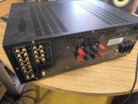
Semi conductors were revised, updated where required, along with capacitors. Front panel connections updated.
I didn't get images of both amps complete, or the main heatsink transistor refit- too busy doing it!
Matching the resistors in all four modules was not completed, another time- along with a paint job and new front panel.
I would have probably gone for Takman carbons. Maybe Vishay Dale RN60D/65D metal films in the input driver stage.

Best manual download: search using: Quad-303-Illustrated-Service-Supplement.pdf

Transistor Outline types https://eesemi.com/to-types.htm

I've tried to find the best resolution, most up to date images of the old manuals. Numbering is on the image jpg:

303 M12160 .jpg

module 12038 issue 10 .png

under 303.jpg


After several iterations:

The input line sensitivity was increased to 1.5V the circuits design max, before interfering with feedback.

C100 increased to 1uF (.68uF limited the lower frequency range to 30Hz due to the result of the overall limitations of components of the 1970's),
lowering the frequency range handling. Using the highest quality PP Film cap available; MKP1839.
Increasing speaker output caps capacitance for similar reasons.

Looking closely to the Hfe of transistors, their gain structure throughout the input driver circuit and for low noise versions/ shielding.
These are in my opinion the best transistor replacements for the 303, old and new.
The (BCxxx) below are listed on the net for the 303, but IMO have too much gain or can't be easily sourced.


Presenting the new list of components for the 303 Power amplifier:


Quantity per PCB amp per module:


TR104 1 x BC556B T.O.92
TR102/ TR103 2 x BC546B T.O.92
TR101 1 x BC109 T.O.18; lower noise shielding / TR107 1 x BC184B (or K) T.O.92; better stability for TR107. 2 x BC184B fine also. (BC550C)
TR100 1 x BC560B T.O.92 Original design Hfe, 'A' versions available, worked fine (BC214C unobtainable)
TR106 1 x 2N5320 T.O.5 Metal shielding, better vibration resistance when heat sunk. Also MJE182G T.O.126
TR105 1 x 2N5322 T.O.5 Metal shielding, better vibration resistance when heat sunk. Also MJE172G T.O.126

The bias trimmer can be 1K along with a change of R132 to 2K4.
Those bourns 3296Y top adjust 25Turn trimmers are good, more stability.


Quantity per main heatsink:

All T.O.3
TR1 TR2 4 x MJ150003G. Legendary power transistors 250W; 20A per device! The originals are 117W.
TR3 1 x MJ21194G regulator


Quantity per PCB PSU module

TR200 1 x BC556 T.O.92
TR201 1 x MJE 182G 3A T.O.126. Or MJE243 4A. Not BC441
TR3 see heatsink

All diodes 4 x 1N4148

MR201 BZX79-C3V and BZX79-C9V1 connected in series, cancelling temperature gradients- voltage stabilisation results.

The PSU bridge rectifier array has the super quiet NXP BYV29X 600 diodes. They required new heatsinks.


Caps:

Cornell-Dubilier CD15 silver mica
Panasonic FM/ FR electrolytics
Wima MKS4 P.E.T
MKP1839 Polyprops

Electrolytic 'T' network capacitor
T-power BHC Aerovox ALN20S1108DF now Kemet. Rated to 100V,
Only one required, uprate to 10,000uF with noise suppressing MKS4,
On a single rail PSU connect the negative through both pins.

Speaker Output caps:
Kemet BHC slitfoils ALP20S1009DD 10,000µF 50 Vdc
Add noise suppression on cap pins, again MKS4.


---


PSU board increase the 6.8K to 10K
a4.jpg


The only other genuine improvement that I didn't get around to was the use of two semiconductor current sources,
in place of R112 and R117 to improve noise and bias stability. Class D regulators i think.
If someone else figures that out, please post it here so there is a definitive list.


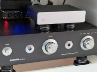
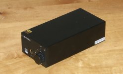
The 'before' images.
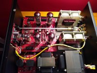
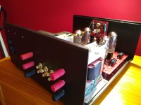
pair.jpg


stock.jpg


The 'after' images:


a1.jpg

a2.jpg
a3.jpg


a5.jpg


Words after the refit?
Alive. Engaging. Open. Seismic.
It's like a heavy cloth has been removed from the speakers.

Attachments

  • a4.jpg
    a4.jpg
    102 KB · Views: 86
  • Like
Reactions: Mooly

Transformer-fed TDA8932 25W/8R mono amp kits

Orders now are open on TDA8932 mono amp kits - feel free to PM me.

Preferred payment method is via Transfer Money Online | Send Money Abroad with TransferWise which typically adds a 2% fee. Our receiving currency is either CNY, USD or Euro in order of preference. PayPal may also be used (in USD) but subject to an additional fee.

Kit for a pair of mono amps with transformer input : 280RMB ($39.50) Built and tested amps, 520RMB ($73) per pair.
Cost-up options to the base level kit as follows. Note the base level kit includes all parts needed for a working amp board, these options substitute various components for those interested in gilding the lily :

Shunt regs (pre-built, pair) : +100RMB
Flat-wire 22uH output inductors (set of 4) : +48RMB (Coilcraft look-alikes and spec-alikes, we cannot be sure they're original Coilcraft).
EE25 permalloy-cored transformer : +100RMB/pair

We are at present only selling amp kits in multiples of two. Kits contain all the parts you need to build 2 off mono amps, excluding power supply. Most of the parts are SMD, the smallest are 0805. If you've only done conventional (through-hole) soldering before this kit could be a handy introduction into surface mount tech. The trickiest part to solder is the TDA8932 itself, it has 32pins on a 1.27mm pitch.

Shipping is in addition and depends on your location and speed of service.

The amp is rated at 25W into an 8ohm load and is BTL - the power rating is a fairly conservative one on music but its not been designed to deliver 25W continuously. The amp IC contains thermal overload protection should its temperature rise too high. The suggested power supply (extra) is a single 24V @3A switching brick for each channel. Thus a stereo setup should have a 24V/6A supply.

Gain is 17dB by default (2VRMS sensitivity), with two resistor changes it can become 23dB (1VRMS sensitivity). If you fit the Aliexpress trafo these numbers become 21dB and 27dB. Since signal transformers are very sensitive to DC you should always use a coupling cap between your source and this amp. 47uF is the minimum recommended value with the stock trafo at 17dB gain, 220uF at 23dB. 4.7uF is fine for the Aliexpress trafo. A too-low coupling cap will result in bass boost due to the resonance between the cap and the trafo's primary inductance.


The original development thread with schematic and technical background is here : Transformer input TDA8932 mono amp


TDA8932 datasheet is attached for those wishing to look in more detail.

<Update Aug 2022>

The PCB is up to rev5 now and accommodates a few options:

a) You can fit a low-noise shunt regulator board in place of U3 (a three-terminal regulator, either LM317 or LM350). To use the shunt you'll need to solder a 0R resistor for R17 and remove R15. C38 isn't fitted when the shunt is used.

b) The transformer footprint accepts a 20k:600R centre-tapped EE25 transformer from Taobao/Aliexpress in place of our custom trafo. https://www.aliexpress.com/item/2251832717562057.html. The reason for choosing this trafo over the stock one is so you can couple to it with a 10X lower value cap due to its much higher primary inductance. It also increases the gain of the amp by about 4dB.

c) Coilcraft flat-wire output inductors can be fitted, part number SER1390-223


1659418360398.png


Old (prior to Aug '22) shunt orientation (earlier PCB revision but orientation the same) :
1660011756242.png


Current shunt orientation - note the latest shunts say 'Low-noise Shunt' on the silkscreen.
shunt_AMP_20220904162359.jpg

Attachments

MC board assemblies

Hypnotised MC board assembly. Complete sans Op amps. Tested (with AD797 and OP176) 100% operational. All HQ parts. Picture of actual board to come soon. Op amps available from Mouser. $50.00

Folded Simplistic NJFET. Hardwired. High quality parts include 4 2SK170BL, 2 2SK369BL, 2 PF5102, 2 BC327. PolyPro RIAA, coupling and output caps. HQ filter caps. Set up for mid/high output MC. Tested, 100% operational. My backup board for many years. $100.00

Just added picture of actual Hypnotised board for sale.

Prefer PayPal and CONUS

Dscf3881-1.jpgDscf3886-1.jpgDscf3888.jpg
Projects by fanatics, for fanatics
Get answers and advice for everyone wanting to learn the art of audio.
Join the Community
507,400
Members
7,868,881
Messages

Filter

Forum Statistics

Threads
405,321
Messages
7,868,881
Members
507,400
Latest member
Marcelbcm