I FINALLY made it here! Just sayin' HI.

I am a longtime Electronic Technician. Been doing it since the 1960's. Winding down now....My line of thinking is kinda basic. I find that quite a few audiophiles think I am way off base when it comes to speaker wires. I guess that is about as controversial as I get. All my life I have bought, refurbished and resold. I still do the same, but at a slower pace. Just saying HI.
  • Like
Reactions: Captain B

Hi from Northern Italy

Hi everybody.

My name is Sergio.

I'm a teaching/performing musician, but since I was a kid I've always been fascinated by all things electronic, especially those that were in any way related to music.
Back then, I was thinking about becoming an electronic engineer, but them ny passion for music had the upper hand.
Anyway, In all these years the passion for electronics never left me, so today, at 59 I'm still building devices such as preamps, filters, tone shapers etc. that I eventually use in my live gigs.

I understand that for most of you maybe it's the other way round, and music is just a hobby aside your main day job... for me it just happened this way, and actually I've never regretted my choice for a single moment! 😎

Best wishes to all of you!

Really tiny RiPole

I am interested by the Ripole design of subwoofer. Somewhat reminiscent of an AMT but for bass in a arrangement that would seem to benefit form force cancellation between the two drivers. This interests me because the macbook pro has extremely good bass for it;s size and reportedly also uses force cancellation (and a whole lot of DSP i suspect too)

So my question.. is it possible to make a really small ripole and have it function as well relative to it's size as the MBP does? the only examples i have seen use 12"+ drivers. is there a reason for that? if i were to build one with 5 or 6" drivers would it work at all? Are there any design tools available?

New Member

Hi. I'm a life-long tinkerer and ham-radio licensee. I got my first license (US Technician) age 12.

One of my first electrical projects was at about age ten. I found an old pinball machine in the dump. I hooked one of it's electro-mechanical score displays to a rotary dial phone to make a rudimentary adding machine. I also nearly got expelled for hooking a car-radio vibrator to an oil furnace ignition transformer and wiring it to the striker plate of the junior-high science lab, giving the instructor quite a jolt when he tried to get in the room.

I started a stereo service business right out of high school, and worked as a technician for a decade or so, and then was promoted to Design Engineer.

Still mess around with AF-to-RF and digital.

de N7JDB/VA7JHI

Dual 604 anti-resonator (counterweight) problem

I have a Dual 604 where the felt pat has fallen off inside the anti-resonator.

There are plenty of pictures available on line of what broken units look like. Even a few pics of best guesses about how to put it together. These pics and posts show more than one idea about how this is held together.

Does anyone have a lead on how this should look before it falls apart. First hand knowledge or a pic of the actual item.

Thanks in advance.

JBL PT waveguide #6815 (VTX F15/F12)

I have a pair JBL 2451 with Truextent diaphragms and the small 12 inch PT Waveguide from VTX (down left on the picture).

Does anyone know the «perfect» crossover frequency and size of the mid/woofer related to off the axis respons in the crossover area?

I hope i could use it around 1000-1200 Hz?


IMG_1367.jpeg


https://www.audioheritage.org/vbull...rade-from-2332&p=371066&viewfull=1#post371066

output repair MMATS D3000.1

I'm working on an MMATS D3000.1 amplifier with the green driver board. It's confusing me as I can't get it to work, but the green board does not have the HIP4080 installed (I thought they removed it in the previous repair attempt). Apparently without the HIP4080 it oscillates, but it has a big noise and a loud POP when turning on and off. The integrated TLC2274 gets very hot, I suppose it will have some problem. I asked in another thread, replacing the IRFB4710 since it was discontinued, with the IRF3710Z, but of course, without having the HIP4080 installed, will the 3710z still be a good replacement for the IRFB4710? What reference are the integrated ones scraped from the green plate installed as a driver?

Musical Fidelity FCD, A journey

Define "Niche"

Bought recently on ebay a Musical Fidelity FCD

No matter your view on MF as a brand and their trajectory from Wembley to Austria this is IMHO one of, if not the most beautiful players ever made. (should be, the stroke of genius was to get actual designers involved apparently)

Some pics of the inside are attached (outside once cleaned!)

This is a TEAC CD-P3500 with a fancy box and a tube output stage (x-10d?) I find it interesting to compare reviews of the two, and lose all faith in 90's hi-fi rags... the evidence is there "MAIN PCB 9155118101" - hats off Mr Michaelson, well played sir!

Also grinding the chips but not the board markings? Come on... OK this was before the internet but surely any idiot reviewer would be able to spot the chipset from it's layout? why the effort? - apparently it was enough 😀

Not to be defeated MF both put a shield above the board and used security torx before you got in :-D I'm laughing because it's not hard to listen to is the truth. I don't know, there maybe something in the; 'huge (valve) input impedence makes op-amps work better', claim...

however, this is presented here as a project:

Plan is to rip the still beating heart out of this and replace it with something "not bitstream" - preferred route is the trusty PMD100 to either TDA1541a or one of the BB (PCM170x?) offerings. Want to avoid CD stuff though

The first thing is to find a donor with separate play/pause buttons and ideally the same dumb display (so no Sony grid) If that's not possible I'll take digital from the SM5840 and go from there...

Accepted already is that I'll be making a new display board the cd-p3500 is super simple

What to do? Oh What to do? 🙂

Attachments

  • FCD.jpg
    FCD.jpg
    612.5 KB · Views: 275
  • not phillips.jpg
    not phillips.jpg
    282.5 KB · Views: 224

Mmats d3500.1 questions for repair

Hi guys. Working on a mmats d3500.1 and the unit goes into protect immediately. I have tested all of the output gets and the power supply fets.they all seem ok. Only thing I found was a tlc2274c OP amp that's toasted.i think its u1 but there is a via on the silk screen. Any ways any one knows what it controls. I don't think it's a fet driver. Any help would be appreciated.

vBias vs Thermal Hystresis

For all the years I have repaired solid state amplifiers, I have just set bias and left it alone. I have never given much thought to the quiescent bias conditions before, during or after Hot laps so to speak. So Now I am trying to understand what is acceptable Bias behavior.
new amplifier BJT outputs mounted on a very large heatsink and fan cooled. Bias set for 100ma per device (20mv across .2ohm emitter resistors) run the amp at 1/3rd power into a 4 ohm load for 15 minutes. the heatsinks get hot, but not so hot you can't hold your hand on them. turn off the input signal. the bias immediately drops down to about 160ma per device and slowly starts to drop as the heatsinks cool. eventually getting back down to 100ma after 10-15 minutes etc.
.
Is That acceptable behavior? or should the bias immediately, or quickly, drop down the the 100ma bias setting? What is an acceptable/normal Bias hysteresis after a hot event? what should I be seeing?
.
the amp seems to be stable otherwise. power on from cold takes about 10-15 minutes for the bias to come up to 100ma and stabilize. and is repeatable. will idle for hours on end just fine. and seems to be ok after a hot run, let it sit and it settles back down, idles ok, no signs of thermal runaway.
.
I have just never considered what happens after running an amp hard, never thought that the bias would climb with heatsink temps etc. just has never been something I have thought through. I consulted all my books, Self, Cordell, Duncan, etc etc etc and I see mentions of the Thermal hysteresis, but nothing that talks about what normal is.

Onkyo M-5030 burnt channel rebuild

Hello all.

This Onkyo M-5030 amplifier has almost fully separated channels (only speaker protection circutry is connecting them) and has a history of burning down one channel...

I worked on it first in 2020 when it had burnt the channel output transistors the second time in a short period (according to the owner).
The previous technician had replaced the output transistors with ones salvaged from another amplifier and also some of the ceramic capacitors.

But both output transistors in one leg of the channel shorted again.

OK, I replaced the whole set with "pulled originals" from eBay, checked other components and the amplifier started up again.

It worked (not in frequent use) ok for ca two years but about half a year ago it was "dead" again - power transitors again.
Some resistors had visual signs of overheating.
I also unsoldered and measured all surrounding components and more than one resistor open.

Long story short - I started to power the amplifier up carefully proceeding step by step.
The VAS stage on regulated power (with output transistors unpowered) acted OK - no oscillation, no excess currents.

Time to connect the power transistors - I placed 100R 10W resitors in B+ an B- rails (to the power stage) and everything was OK.

Why not use a variac or DBT?
The VAS stage gets itself powered via regulatros which do not work with lower mains voltage (Onkyo dropped that complexity in later models and did not use it earlier if my memory serves me correct):
M-5030_schematics_02_power_reg.jpg


So far so good.
But when I replaced the rail resistors with 10R ones then "magic smoke" was let out.
To my surprise the output transistors measure (in disconnected from board state) ok with a DMM (in diode mode) but at least one 0,33R ceramic resistor in their collector lines is cracked.

Now the next step is to check all components again but after that all advice is welcome how to proceed with poering the amplifier without burning it again.
So guys, walk with me ...

Preamp heating up

Hello,
I have a question that may be considered as a general one or it may go to more details and become a special case.

My preamp becomes unusually hot after even a short use. Being a preamp, it does not need to work hard with those power transistors generating enough juice to feed the speakers. Why do they turn into hot coals in my case? Should I try to replace the transistors that sit on the radiators?
Another concern is the very sensitive VR adjustments of EQ Amp midpoint. Very hard to set it to a stable required rating. Can that be a possible cause for the output transistors to heat up? There are three points of adjustments for this preamp.
Where should I look further to try to fix the overheating problem?

The preamp is a Yamaha C-50.

Attachments

  • C-50.png
    C-50.png
    57.4 KB · Views: 105

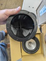
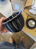
3d Printed Mid Enclosure - Should I stuff it?

These are the mid woofer enclosures I was talking about in my other thread. They mount to the inside of the front baffle behind the mid.
You think I should stuff this with some wadding or just leave them the way they are?

I added the STEP file for the enclosure if anyone wants to use it. You can scale it up or down for whatever size driver you are using. Anyone with a 3d printer you know can print it out for you and scale inside of their slicing program

Attachments

  • PXL_20240607_192951981 (1).jpg
    PXL_20240607_192951981 (1).jpg
    515.2 KB · Views: 202
  • PXL_20240607_192956739 (1).jpg
    PXL_20240607_192956739 (1).jpg
    380.9 KB · Views: 199
  • PXL_20240607_192958952 (1).jpg
    PXL_20240607_192958952 (1).jpg
    399.1 KB · Views: 194
  • Mid Enclosure V2.step
    Mid Enclosure V2.step
    368.6 KB · Views: 60

Hello from Rochester

Hi all, I'm venturing into separates for the first time after building a discrete RIAA stage. I recently picked up an SGA Unity line stage which appears to have been built by Steve Giunta from Corey Greenberg's design in Stereophile, and a Hafler 9180 to drive a pair of Hansen-Zylberberg speakers I rrefurbished the insides of. Right now the Hafler is having an issue with DC on the right channel during startup that caused oscillation I'm working through.

Turbosound Inspire iP500 question

I have a pair of Turbosound Inspire iP500 powered speakers which have the same problem.

One failed maybe a year ago by not powering up and upon opening the amp module an electrolytic cap in a potted area of the board was domed on top. Given I don't see a way to remove the potting without damaging the board, I haven't fixed it.

The other one failed in the same way and likely could be the same cap.

Is it possible to wire these up to use an external amplifier with either a passive or active crossover or does the stock amp do some sort of processing that would make the speaker sound bad doing it that way?

For Sale Glassware / Broskie 12B4 CCDA Line Stage Kit with Primo Parts

I have an original John Broskie 12B4 Constant Current Draw Amplifier kit that I bought eons ago, but never got around to starting. It's now unobtanium.

Broskie's kits feature top quality parts, from the PCB to Nichicon and Panasonic electrolytic caps; WIMA metal films, etc. I also bought premium 600V RTI 1 MFD caps (those cost me $23!). Includes the 4 tubes, mounting hardware, etc. etc. Selling for under cost.

$159 + shipping

Attachments

  • 12B4 CCDA Kit.jpeg
    12B4 CCDA Kit.jpeg
    773.1 KB · Views: 159
  • Like
Reactions: G600

Hello from Norway!

Hi!
Long time lurker, first time poster.
Not quite sure where or how to start, but been into diy audio for a couple of years now. Been tinkering with mechanics and electric/electronics for most of my life doing small repairs and troubleshooting like resoldering loose connections and stuff like that. Recent years making some amplifiers. Started with the DoZ (don’t really care for the name) Found the schematics and soldered it up on a perf-board, and powered by a Meanwell smps.
Since made some ACAmini’s and 2022fe’s, H2’s and currently working on a F5m. Tested and working on enclosure. More projects in the queue.

Have learned tons from you guys and looking forward to learning a lot more.
Consider myself a complete noob, but know enough to know that it is MUCH I don’t know.

Lars.
  • Like
Reactions: xa488

The Boominator - another stab at the ultimate party machine

First a picture of the finished beast on the scales (it weighs 26 kilos with batteries).

An externally hosted image should be here but it was not working when we last tested it.


Then a couple from the testing where you see both sides:

An externally hosted image should be here but it was not working when we last tested it.


An externally hosted image should be here but it was not working when we last tested it.


An externally hosted image should be here but it was not working when we last tested it.


The design parameters for this was to make the optimum comprimize between several things. These being:

- best possible sound quality
- loudest possible output
- longest possible battery life
- lowest weight possible
- smallest volume possible
- lowest cost possible
- simplest possible construction

Since I wanted low weight and high output I very early settled on a design with 4 10" pro woofers mounted magnet to magnet inside the cabinet to give added sensitivity and free structural strength which meant I could use thinner plywood than would normally be used for baffles. I also quickly settled on 7 layer 12 mm filmed birch plywood, both because we have a lot of it at work and because it very very rigid.

I used 4 P.Audio HP10W woofers becuase they're cheap, sounds great, and not least because they had the perfect depth for magnet to magnet mounting. For top end I used 4 MGR CH-100 piezo tweeter. Again low cost and good sound quality was the primary factors. It's not really filtered, it's got a 0.22 mH coil to flatten the peak of the woofers and filter above that point. The piezos only has 3 Watts 150 Ohm carbon resistors in series. With a 150 Ohms resistor, they sound great as long as the voltage across them is not too high.

The cabinet is built as two separate bass reflex cabinet with a battery and electronics compartment in the middle. The holes on the front are cooling and cable access, while the handles on the sides double as reflex ports.

It's designed to be used outdoors, so I chose a Qbox of 1.1 tuned at 82 Hz (my little nod towards 41Hz.com 😉 ). Trying to go belong 100 Hz in free-field is nonsense if you keep the other design parameters in mind. It's better to have a good middle bass performance to compensate for the lack of real sub-bass.

It's loud! The sensivity is about 98 db/watt because of the double woofers and the magnet to magnet construction. With the amp giving about 50 Watts total peak power output, it should be around 113db total in peaks.

The choice of amplifier was pretty obvious. I had to be a Tripath based amp because of the low cost, good sound, and long battery life. The choice fell on the excellent amp6basic kit from www.41hz.com. Here shown with and without cooling plates. (I made two beasts at the same time, one for me, and one for a friend of mine.)

An externally hosted image should be here but it was not working when we last tested it.


An externally hosted image should be here but it was not working when we last tested it.


The optimize battery life I installed 4 8 Volts 250 mA solar cells from siliconsolar.com, 2 in series on either side. The battery life solely on battery is around 50 hours at maximum music power. And with reasonably sunny weather, they can probably last several months at fairly normal power levels. That remains to be tested.

An externally hosted image should be here but it was not working when we last tested it.


I also added a switch mode recharger from batteryspace.com, and a standard car USB power supply. The batteries are 2 standard 12 Volts 7 Ah SLA paralleled and stacked on top eachother.

Here's a few more pictures from when I put them together.

An externally hosted image should be here but it was not working when we last tested it.


An externally hosted image should be here but it was not working when we last tested it.


Cheers! 😀

Wurth inductor, real or fake?

Hi,
I am building a few TPA3255 amps and unfortunately, in the few months that it took me to draft all the PCBs etc, the inductors i have chosen and the alternatives that i know of have gone out of stock in the suppliers available to me :-/ I am too slow i guess...
Anyways, i took the chance and ordered 3 of them to Aliexpress. Overall i dont have a bad experience with Aliexpress, and i believe one can get genuine parts there, but well, not having any known legit example at hand, i have no idea if what i received has any chance to be legit.
The part in question is Wurth Elektronik 7443631000 10uH 16A power inductor. See pictures below. The markings and date codes seem possible, the only thing i am missing is a dot indicating the beginning of the winding but i am not sure if this is always there.
Some details that i think could help are:
the black enclosure has a shine to it, it is not matt, most specially the sides
on top and bottom, the rim of the enclosure is a little higher than the inner surface, i hope i captured it well in the picture below
there is a very visible mark where the joint of the top and bottom is.

Anyone has any of these or similar from Wurth or even a good picture that can help me to validate these? thanks a lot!

1719499795770.png


1719499858391.png
  • Like
Reactions: analog_sa

Building a theatre 2-way system with matching ceiling speakers

SB17NAC35 with SB26ADC build - Please help

I built my speakers from a kit 20 years ago and am a relative newbie to diy speakers. A little knowledge is a dangerous thing so I’m here to ask you for some advice.
I’m a theatre buff and looking to “refresh” my 20 year old speakers with a new tweeter, woofers and crossover. Currently, I have the Vifa d25ag tweeter and two P17WJ 6.5 inch woofers in very pretty 50 litre ported enclosures. The centre speaker is a different shielded kit that never really matched the L/R’s. The surround, rear and sub are Wharfdale and I’ll keep them for a while.
I was very happy with the Vifa’s but have since ordered the Anthem MRX 1120 and plan to put in 4 new ceiling speakers with enclosures. I was considering the RSL C34E ceiling speakers but they are expensive once imported into Australia. For the same price, I can build my own which has the advantage of using the same tweeters, drivers and effective enclosure volumes to match the main speakers, ensuring the same timbre from each.
I’m after an accurate, low distortion and a flat response curve that will carry audio down to 90 hz where my subwoofer crosses over. The fronts are 50 litres with holes for a 1 inch tweeter, two 6 inch woofers and 2 ports. My plan is to use:

Front speakers:
SB26ADC-C000-4 (recessed 18mm to time align to woofers)
SB17NAC35-8 (2 drivers run in parallel from a single crossover to appear as 4 ohms and increase power handling and sensitivity)
50 litres, 2 ports, 2000 hz / 2nd-order Linkwitz-Riley crossover

Ceiling speakers (in enclosures angled at 45 degrees down directed at my seat):
SB26ADC-C000-4 (recessed 18mm to time align to woofer)
SB17NAC35-4
25 litres, 1 port, 2000 hz / 2nd-order Linkwitz-Riley crossover

Reasoning:
I like the idea of these drivers since they reportedly have low distortion and a flat response curve at a good price and don’t seem to break up as badly as other aluminium drivers. I live in the tropics (hot and very humid) so paper drivers are out of the question.
Ceiling speakers: The sensitivity of the 4 ohm tweeter and 4 ohm woofer are the same so no attenuation is necessary.
Front speakers: These need more power than 60 watts so I’ll use 2 woofers. The 8 ohm version of the woofer has sensitivity about 3.5 db less than the tweeter. By running two 8 ohm woofers in parallel from a single crossover, it will increase sensitivity by 3 db so no other attenuation is necessary. These should sound the same as the ceiling speakers but handle more power.
Enclosure volumes: The SB site gives the main values of SB17NAC35-4 as:
Diameter: 12.26 cm, Fs: 32 hz, Qts: 0.32, Vas: 33 litres – giving an enclosure of 19 litres (per driver)
www.audioexcite.com >> SB Acoustics SB17NAC35-4 tested the SB17NAC35-4 as:
Diameter: 12.26 cm, Fs: 37 hz, Qts: 0.42, Vas: 21 litres – giving an enclosure of 26 litres (per driver)


Questions:
Are these drivers the most accurate reproduction across the range at this price and if not, which are significantly better?
Will these give me a big improvement over the 20 year old Vifa’s?
Will this go low enough to seamlessly meet the subwoofer at approx. 90 hz or should I go for a 3 way system?
Are the enclosure volumes okay? I’ll use an online calculator for the ports. I can stuff the speakers with solid blocks to reduce volume if it is too big.
Is a 2000 hz / 2nd-order Linkwitz-Riley crossover the best option?
Is using two 8 ohm drivers in parallel the best option for the mains and will it sound the same as a single 4 ohm in half the enclosure volume?
Is setting the tweeter back 18mm necessary to time align to the woofers (I read that it should be 18mm for a similar combination Yet another 6+1 construction: SB17MFC35-8 + SB26ADC-C000-4 )?
Am I supposed to invert the tweeter connections on the crossover to make sure phase is correct or this accounted for by the 18mm offset?
Any other advice? - Thanks!

Attachments

  • 2008-07-18 023.jpg
    2008-07-18 023.jpg
    340 KB · Views: 217
  • theatre.jpg
    theatre.jpg
    180.5 KB · Views: 230

Updating Philips / ADK 3540 (I think)

Hi - I think I have a pair of Philips kit speakers that someone took the time to put together in what seems to be a decent manner (dovetailed walnut cabinets).
Drivers are AD 10100/W8, AD 5060/Sq8 and AD 0160/T8. The kit seems to be an ADK 3540 but I've seen a close match that is referred to as a Philips System 20. I'm not 100% sure which it might be (if either) as I can't exactly match the cabinet dimensions (close though).

I plan to move the inductors so that they aren't lined up in parallel, but am wondering what's the best replacements for these caps? The speakers sound pretty good as is but I'd like to see if there is room for improvement. I read that the high end on these can sound scratchy and that is currently not the case at least to my tinnitus addled ears.

One other thing - the AD10100 had foam dust caps (now mostly dust with a couple of small foam pieces) - from the bits I estimate a 70mm cap with a weight of about about 3 grams - assuming that sounds about right would you replace with cloth or felt?

Thanks for any advice.

Attachments

  • IMG_0348.JPG
    IMG_0348.JPG
    400.2 KB · Views: 71
  • IMG_0369.JPG
    IMG_0369.JPG
    459.6 KB · Views: 82

Speaker rebuild

I've got a speaker cabinet that originally had 6 8" full range drivers in it which I repurposed with four 8" woofers

https://www.parts-express.com/Dayton-Audio-DC200-8-8-Classic-Woofer-295-310?quantity=1

A sealed back 8" midrange and an Eminence APT-80 tweeter mounted on a piece of wood to make it fit the 8" driver hole.

The cabinet is barely wider than the 8" drivers are which I know kills bass response.

I'd like to design a new box. It will either be:

1. Wider and deeper with drivers still in a vertical row.
2. Wider and deeper with woofers in a vertical row and midrange and tweeter in their own box.
3. Woofers in a square pattern like some guitar cabs have them with the midrange and tweeter in their own box.

I am also toying around with the idea of using four of these in a square arrangement

https://www.parts-express.com/Dayton-Audio-DC250-8-10-Classic-Woofer-295-315?quantity=1

as they have better bass response than the 8" and possibly doing the same with the 8" and having the midrange and tweeter in their own box.

For these designs I will be using an open back midrange which for the vertical arrangement with the mid and tweeter in the same box will require a chamber for the midrange.

Now my thought is to use the 10" for the lower bass and I initially thought of a passive crossover about 80Hz, but that requires expensive components due to the values they have to be so I'd possibly go active.

Here's a photo showing the designs.

Speaker 1.png


Speaker 2.png


If I decided to go through with this what would each box size need to be for the listed drivers? Also what would be a good midrange driver to use and what should the cabinets be made out of?

That said would a 4 10" guitar speaker cabinet (provided I can find one that is sealed) be good enough for 4 10" woofers?

I honestly like the 8" and 10" driver arrangement as it just looks cool, but if 1, 2 or 3 will get me the bass response I want then I'd go with the best of those designs.

For a cabinet covering I was thinking maybe truck bedliner coating along with metal corner protectors and for the 10" cabinets I might install casters. For the separate cabinet designs I would include something to keep the speakers from sliding around on each other at high volume levels.

LED tubes too "hot" for my ballast. Junk Box Solution?

Picked up a set of LED tubes for a shop florescent light fixture. Manufacturer states on package "Works with most ballasts". Well, not mine apparently - hums audibly moreso than the florescents and eventually trips the ballast breaker, which I assume is thermal.

I went through several cycles of use in this state, finially getting up the gumption to do something about it. Working solution uses one of my Variacs, set to "70" on the dial. A bit less light, but no longer trips the breaker. I have to put a step ladder atop a ping-pong table to access the fixture / tubes... AC socket were it plugs into is much more easily accessible.

Since I have two other Variacs on hand, I could let it sit for years that way, but was hoping for a less "hardware intensive" solution - like a series diode and capacitor maybe. The lamps being returned for a refund, or getting new lamps that work with the ballast I happen to have, are not viable solutions for me.

I suppose I could find a transformer with a 30 - 40V secondary and get away with bucking down the AC line to suit my predicament. Unsure what the current is, as my Variac doesnt have meters, but it would be possible to find out.

Any ideas that wont burn the shop down? Thanks!

introductions - new members? (just curiosity)

hello all,
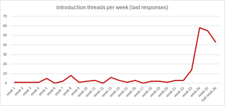
anyone else noticed this sudden increase of introductions?
(for simplicity I used the last reply date for the threads).

240628_intro.png

just to be clear - I am totally happy about this fact and warmly welcome all new members!
DIY audio is a great way to learn self-efficacy and science.

but it stil puzzles me - is this increase in introductions correlated to new members?
or is there a new welcoming message, suggesting to introduce oneself?

stv

EDIT: corrected the days per week count - thanks to @Ultima Thule

Altec 288-8G Compression Driver with Altec 805B Multicell

In this post I test Altec 288-8G Compression Driver with Altec 805B Multicell.

I borrowed the horn from my brother.

IMG_0002_480x480.jpg
IMG_0001_480x480.jpg


Specification

Compression Driver


  • 2.80" Diameter Voice Coil (71mm)
  • Aluminum diaphragm
  • 7.1" outside diameter for compression driver body
  • 29.3 lbs compression driver weight (13.3 Kg)
  • Alnico magnet
Horn

  • 40 x 80 coverage pattern
  • 500Hz Cutoff frequency (Fc)
  • 62cm wide x 34cm tall x 55cm deep
Measurements

Frequency Response


I measured the horn with a 2m mic distance. Above 1kHz my measurement is gated to 4ms using 1/24 octave smoothing. Below 1kHz the repones is ungated and 1/3 octave smoothing applied. Generally we see a reasonably smooth response with a midrange emphasis centered at about 2kHz. The horn loads strongly down to 400Hz with very little first order reflection near the the horn's cutoff frequency which is published as 500Hz. The diaphragm is breakup free until 13.5kHz.

Altec_805B_with_288-8_Compression_Driver_480x480.png


Below is the horizontal off-axis colored polar map using the same 2m mic distance.

Characteristics

  • 90 degree coverage (500Hz-1.5kHz)
  • Widens to 120 degrees (1.5kHz-17kHz)
  • High frequency output drops when measuring directly in front of each cell


Altec_805B_with_288_Compression_Driver_Horinzontal_Off-Axis_480x480.png


Time Domain

Conducted in the near field using a 20cm mic distance.

Altec_805B_with_288-8_Compression_Driver_CSD_480x480.png


The burst decay shows some stored energy in the treble region.

Altec_805B_with_288-8_Compression_Driver_BD_480x480.png


Distortion

I measured distortion with the 20cm mic distance. SPL level was set at 85dB and 95dB referenced at 1m. I set a fixed resistor L-pad using a 20w 7.5ohm and 1.5ohm (R1 & R2) which provides about -15dB attenuation. This brought the amplifier up out of its noise floor (Hypex FA500). Above 1kHz we see H3 and H4 at very low levels while H2 dominates. H3 for the 95dB signal is only 0.015% for the 1kHz region.

Altec_805B_with_Altec_288-8_Compression_Driver_85dB_1m_480x480.png


Altec_805B_with_Altec_288-8_Compression_Driver_95dB_1m_480x480.png


Multitone is shown below for the same 85dB and 95dB test signal levels.

The 85dB test signal shows 70dB dynamic range for the 1.5kHz region reducing to 60dB for the 10kHz region.

Altec_805B_with_Altec_288-8_Compression_Driver_85dB_1m_IMD_480x480.png


The 95dB test signal is unchanged for the midrange but we see 10kHz reduce to 50dB dynamic range.

Altec_805B_with_Altec_288-8_Compression_Driver_95dB_1m_IMD_480x480.png


Contour Circuit

The horn has a strong midrange presence along with some coloration near the horn's cutoff frequency. So I decided to develop a basic high pass filter along with a contour circuit. I settled on a LR3 high pass filter to eliminate the coloration in the 500Hz region. I then implemented an parallel LCR contour to bring down the 2kHz region. The raw response is shown in red, the blue response is with the LCR, and the green response is with the high pass filter.
Altec_805B_with_288-8_Compression_Driver_Crossover_Circuit_2567_480x480.png


Subjective Listening

With contour circuit No.2567 in place, I've summarized my listening impressions.

  • Spatial and enveloping treble due to 120 degree wide coverage
  • Despite the class D amplifier, the sound had some typical H2 smoothness.
  • Missing upper treble detail
  • Some horn coloration across its bandwidth
  • Strong presence on vocals (voice modulation easy to follow)
  • Some masking of soundstage depth
Overall the 288-8G with the 805B horn offers an entertaining and enjoyable listening experience if you can get past the slight horn coloration which masks overall clarity. A super tweeter may offer some resolution improvement for the upper treble, but the coloration through the midrange would still exist. For example the burst decay is shown below with the contour circuit in place. Perhaps there are methods to improve this which is beyond the scope of this post.

Altec_805B_with_288-8_Compression_Driver_Crossover_Circuit_2567_BD_480x480.png

Hi all, where do i start?

Hi all,

I'm exploring if diy audio would be an interesting hobby to develop. Could anyone point me to where i can find related resources?

Topics interested are on DACs and ampfliers:
  • Is there a "industrial standard" or checklist to reference for diy?
  • What is the latest trend for these devices?
  • What chips are the "go-to" today? (example like ICs for DACs, transistors for amps)
  • Any advice on building or designing workflows, tips and tricks, etc.

CamillaDSP - is it possible to run more than one instance?

hi, I have audio in three rooms which will eventually total 29 outputs. Presently using DCX2496 crossovers and rather than acquiring another of these often problematic devices for the channel expansion I‘m looking to replace them all with CamillaDSP.

I usually but not always have audio playing in only one room at a time. In the interest of keeping the configuration file(s) more manageable and to perhaps reduce the total processing load, is it possible to invoke more than one simultaneous Camilla instance each with it’s own separate configuration (i.e. one for each room)?

I’m on a Mac and use RA’s “Loopback” for routing so it’s easy to create/route individual multi-channel pseudo-devices for each room‘s ins and outs.

BTW: Really impressive piece of work - thank you!

Looking for old Econowave schematic

A couple years ago I bought crossover components for a 2 way Econowave design using the B&C DE250-8 driver and a 15" Altec woofer. All I have are the parts values for the 1.1 Zilch circuit board I also bought. If someone kept up the schematics and could find this one, I'd very appreciative. I may have R1 and R2 switched.

L1 1mH
L2 4.5mH
C1 5.6uF
C2 12 uF
R1 2.7
R2 4.7

2020 DIY Sony P-Channel VFET lottery amp #044

I have decided to let my original / first run single-ended Class A VFET lottery amp go to an established fellow diyAudio member that will give it the proper attention and use it deserves. Very little time on this one, maybe two weeks and has sat on a shelf ever since. Carefully and expertly assembled by a dedicated longtime diy'er with IPC J-STD and A-610 certifications. This unit is built and functions exactly as designed and intended. Amp is completely stock, but will include an optional PS board and a couple of transconductance (current output) amplifier front end PCB's designed by Mark J. that I didn't get around to trying out. Price is SOLD + PP G&S fee + actual shipping due to inflation and just the rarity / keepsake / collector nature of this fine amplifier. US sales only. I will pack carefully and ship with UPS, tracking information provided. Thanks for looking.

Attachments

  • IMG_0260.jpg
    IMG_0260.jpg
    414 KB · Views: 133
  • IMG_0262.jpg
    IMG_0262.jpg
    403.3 KB · Views: 136
  • IMG_0345.jpeg
    IMG_0345.jpeg
    667.4 KB · Views: 130
  • IMG_0346.jpeg
    IMG_0346.jpeg
    269.8 KB · Views: 144
  • Like
Reactions: ItsAllInMyHead

Front speaker location options

My car has only 4” x 6” speaker holes on the dash for front speakers, yellow arrow. However, there are 6” holes on front door for factory audio upgraded option, red circle. Mine has only speakers on the dash.

IMG_8600.jpeg


I have a pair of 5 1/4” component speakers. I’d like to use it for my front speakers. But as said, the front speaker holes are limited for 4” x 6” size and cannot be installed the 5 1/4” speakers—the magnet will stick to the a/c vents inside the dash.

I wonder whether I should drill the front door cards to install the 5 1/4” woofers in the red circle and put the 1” tweeters on the dash, yellow arrow. OR, I should buy a new pair of 4” speakers, either coaxial or component, to install on the dash at one point.

For Sale 10 x Line array waveguides simlar to B&C ME102

I purchased these waveguides for this project: https://www.diyaudio.com/community/threads/constant-curvature-tweeter-array.388439/#post-7275853
but they don't workwith extension horns in a tightly curved array so they are now surplus to requirments. I will accept any offer which covers postage from the UK to where you are! you have to buy all 10 as I'm clearing out things for a move.

Source for genuine TDA1543s

Hi,
after i heard a 16xTDA1543 DAC I would like to build one myself, but most of the ebay suppliers are a bit strange. The chips they sell all have the same number on them. Are these relabeled fake chips or what is going on there ?
Do you know perhaps where to buy genuine TDA1543s or TDA1545s ? I like the idea to use them in parallel and avoid a complex output stage.

Bass frequency issues regarding bass. Speakers are TL/Ported?

Hello everyone its Bazza.
So an add on to previous thread, about the bass. Iv done a low frequency test from 25hz to 150hz amd this is what I got. Up to 49hz nothing 50hz it begins up to 75hz. From 75hz to 120hz ish flattens out onwards to 150hz.
What I don't get is this, songs that I know produce the hi pressure in the gut type bass I should get...but...I don't! I get instead a vibration a heavy type, can feel it on the floor the sofa everywhere! !. I don't understand? During the sweep 25hz to 50hz I got no vibration, from 50 to 75hz good good bass no issues with vibration it wss solid.
Please guys n gals helpe me out

Constant voltage PSU

Hi boys,

I am working on my pp class A amplifier. I am currently working on PSU of the Driver stage (my amp have only driver and power stages). The driver is formed as LTP using CCS in the cathodes. I found out that i need constant voltage supply for driver. Fluctuating voltage in the power supply network +-10% would greatly affect the operating point of the driver.
The picture shows the whole situation. In the red frame is the voltage "regulator" that I designed. Unfortunately, I am not a friend of simulation. What do you think, can it work well? Of course, I take into account that zener diodes are not very accurate and have a thermal coefficient, but that is nothing compared to the +-10% fluctuation of power networks. I also know about a large amount of zener diodes noise, but it should be cancelled in the differential pair of power stage. The driver differential pair has a constant current draw, so I don't have to worry about voltage regulation.
What do you think of my circuit? Would you change anything?

Thank you

Jan

Attachments

  • Constant voltage PSU.jpg
    Constant voltage PSU.jpg
    399.4 KB · Views: 146

New ADSP21489 4in/8out board with front panel and ES9028

Hello,
I recently bought this card on Aliexpress: https://www.aliexpress.us/item/3256805054463128.html

WhatsApp Image 2024-02-18 at 12.19.01.jpeg


which should be the most updated version of the card in this thread:
https://www.diyaudio.com/community/threads/cheap-adsp21489-4in-6out-pcm1798-board.339777/


The software that the seller provided me has serious problems, it is not possible to insert the exact values in the Gain and Q parameters because by moving the mouse from the input box or simply passing the mouse arrow over the input box, the value changes randomly, setting maximum or minimum values
I've attached some videos that shows the issue

The software installed is named DP48X control software (version 1.8)
On LCD display is also possible to view the firmware version:
WhatsApp Image 2024-02-18 at 12.19.34.jpeg


The boad sounds very well and it's possible to connect Amanero card directly, but the control software works very bad, so is impossible to set corret values

Someone bought this card with the same ploblems and solved the issues?

Regards
Francesco

Attachments

  • EQ issue.mp4
    5.8 MB
  • GAIN issue.mp4
    2.1 MB

gas competition 7000.1

i a few month ago tried repairing this amp, i have since then made progress and found the problem.

square wave at power stage mosfets leg are fine without mosfets in and with them in the square wave will not come down to ground propertly. ive checked the pulldown resistors which are 1 10k ohm resistor per 6 mosfets, when replacing the pulldown resistor with a bigger 1k ohm resistor the square wave is now present with one mosfet and after installing mosfets one after the other the square wave gradually dissappears. gate square wave on buffers are present all the time. buffers where originally c2814 but where replaced by bd237 but did not make any difference. any thoughts?

Soft start circuit design and other psu issues

I do not see how the soft start circuit can be made into a slow charge for a large capacitor bank in a high powered class A amp, as either the load on switching is VERY high, or the dissipation in the bypass resistors is very high. without the class A load, it is no problem, with the load, it is extreme. I think one would have to also switch the load after a duration..... which means more relays....

If any interest, I can post an LTspice sim using inductors for transformers.....

DIY-Speakers placed high up – downward angled baffle or driver(s)?

For our kitchen area, I'm planning to construct some compact 2-way speakers (17 cm wide x 25 cm tall) and integrating them nicely with a wardrobe.

The wardrobe ends currently at a height of 2,25 meters, which means both drivers will be considerably above ear level (given this is a kitchen, one would mostly stand upright). Speakers will be about 2 meters apart from another, listening distance will be anywhere from 1-3 meters.

What I am really pondering about (and couldn't find easily information on):
  • is it advisable to construct an angled baffle to have drivers fire downwards?
  • will it be worthwhile to place the tweeter below he woofer?
  • before committing to a design, would you advise me to make some experiments/conduct any measurements first (I suspect so) ?

The build doesn't have the ambition to be audiophile at all (it will be first for practical listening, great sound is plus!), but please do let me know your advice if tilting will be worthwhile to look into.

Keen to hear your thoughts! And thanks upfront

I have a confession to make

A minor or a major sin? You decide.
Using a garage sale box and some bits from the shed to make a new set of party speakers.
Going though my spare parts and trying to figure out a crossover to go with the hodgepodge of drivers I'll be using I couldn't make a decision.
Went on eBay this AM and found some Jaycar 3-Way crossovers from about 20 years ago [ 2004 catalogue says $57- each 200 watts and frequency divides to suit the old Tandy 2" dome at 1500 and 5k-.
It's a junk box why not use a junk XO? So I bought 2.
Near enough good enough?
I will need to put a zobel on the woofer but that's from stuff in the junk box and I finally get to re-use the old Tandy dome
  • Like
Reactions: kevinkr

SPDIF cable to connect a usb-to-spdif converter to DAC (no USB)

Both ends of the converter (converter link) and the DAC (DAC link) (this is just a sample image of another DAC but the COAX input seems to be same/similar for all DACs) - seems to be using RCA female sockets.

I can get the 75ohm RG6 cable of various brands (Belden/Canare)/etc) but I'm unsure of the connectors to use. Would normal RCA connectors suit (with/without modifications)?

Thanks

Tuned Sound Amplifier/Receiver for the VLF Christmas Eve transmission from SAQ, Grimeton, Sweden

The only remaining working Alexanderson Alternator is transmitting again this Christmas Eve from SAQ Grimeton, Sweden (near Gothenburg city) on 17.2 KHz. (congratulations to Sweden for preserving and operating the Alexanderson Alternator).

I would like to receive and record this transmission here in Cardiff, Wales. The Alexanderson Alternator generates the 17.2 KHz carrier with a power level of 200 MegaWatt. At that frequency (in the audio spectrum) and at that power, propagation is likely to be global (subject to signal to noise constraints).

I'm building a simple receiver feeding into a preamp plugged into my Laptop PC that is running a sound recorder program. So far I have wound a 35 turn coil using many-stranded Litz wire onto a long ferrite rod and plan to resonate this at 17.2 KHz with a good quality capacitor. Then feed into a preamp built with a second tuned circuit. Simply then connect to the Laptop PC using 3.5mm Jack plug.

Can anyone advise me as to the best way to build this simple receiver? For instance will the ferrite rod be enough of an antenna or should I connect to a long wire? Will a preamp with effectively two tuned circuits likely provide enough gain? And so on....

During my reading I understand that a problem with VLF reception is signal to noise, there are several unavoidable noise sources such as global lightning storms.

Any kind of comment gratefully received.
  • Like
Reactions: Aridace

Apogee AE-12A can work in 2024?

Guys,
There is a pair of Apogees AE12A's cabinets that are offered to me , looks like they are dual 18's .

The price looks reasonable for the cabinets only, I mean worst case scenario (busted drivers)

Good scenario: they will kick for some more years

There is a special on 2 drivers right now
LaVoce SAF184.01 - 8 149bux
And
Beyma 18WRS600 - 8 159bux

Does any of those will work on the Apogees?

Or I need something like 18TBX100

Found this specs in the net
Enclosure type: rectangular, optimally vented bass
Format: Electronically-coupled
Driver complement: dual apogee dd1803, 18" cone
Nominal impedance, 8 ohms each driver
Frequency response: 30hz - 105 hz +/-3 db, 1 meter on axis
Sound pressure level: 128db continuous, 134 db peak @ 1 meter
Max power handling: 1200 watts continuous, 4800 watts peak (600/2400 each driver)
Input connectors: neutrik nl4mp speakon
Rigging hardware: 12 guage steel nutplates on both ends backed with steel reinforcing brackets. accepts 3/8-16 threaded fasteners.
Dimensions: 44.75"W x 30"H x 22.5" d
Weight: 85 lbs.
  • Like
Reactions: Booger weldz

Measure secondary voltage with a digital multimeter

Hello
I have a power transformer that works out of 120V and I would like to find out the secondary voltage that this transformer brings out.
As you can see on the attached pictures, the left side shows four wires and the right side shows one pair, which is 120VAC. What (pairs of) wires from the left side carry the secondary voltage?
Thanks

Attachments

  • pic1.png
    pic1.png
    47.1 KB · Views: 66
  • pic2.png
    pic2.png
    17.5 KB · Views: 60

Hello all!

Hi everyone.

My name is Colin, and I'm interested in "trying" to make my own record deck and speakers. I have access to Rohacell foam so I am hoping to try and thermoform the cones from this material and use it to make an ultra lightweight record deck like the planar 10. I have been able to figure out how to get Rohacell as thin as 0.8 mm and I am aiming to hit 0.5 mm (not for speaker cones, a different project)

So, hi !
  • Like
Reactions: stv
Projects by fanatics, for fanatics
Get answers and advice for everyone wanting to learn the art of audio.
Join the Community
507,384
Members
7,867,992
Messages

Filter

Forum Statistics

Threads
405,276
Messages
7,867,992
Members
507,384
Latest member
RMCO