Quite a few recent line-level projects here on diyAudio, are using Switch Mode Power Supply ("SMPS") wall warts to convert mains AC into the DC needed by audio circuitry. To name a few recent examples, the Starving Student II headphone amp, the First Watt H2 effects box, the B1 Korg NuTube preamp, and the Amp Camp Preamp+ (with headphone amp) are all powered by external SMPS warts. It's definitely a trend.
However, the 50-350 kilohertz switching circuitry inside SMPS modules, does make some members nervous. These folks are very concerned that high frequency noise on the DC supply, could compromise the sound quality of audio circuits. They desire a DC supply having very little high frequency noise, or, ideally, none.
I felt that, IF these pieces of audio gear could tolerate an additional 100 - 150 milliohms of resistance in series with their DC power supply, THEN we can build passive filter circuits to eliminate much of the SMPS high frequency noise. Admittedly I only studied their designs briefly, but I did come to the conclusion that all of SS-II, H2gen, B1Korg, and ACP+ can indeed tolerate an extra 0.15 ohms in series with the DC supply. So why not build a filter with a little extra series resistance, and see what happens.
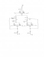
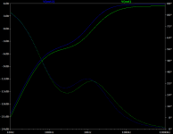
After some experimental tinkering, the circuit schematic in Figure 1 took shape. It has two stages of LC filtering, built 100% with through-hole components for easy soldering. Noise attenuation at 50 kHz is about 40dB (i.e. 100x); while at 200 kHz, noise attenuation is about 65dB (1700x). Input to output DC resistance is about 100 milliohms on the PCB. Then we need to add the resistance of external wiring (about 16 milliohms per foot for AWG-22).
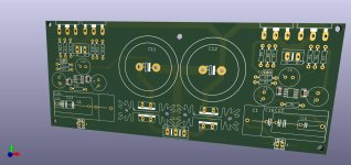
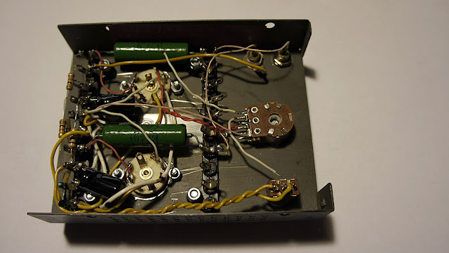
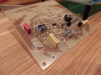
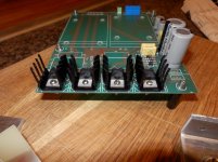
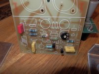
The filter circuit is laid out on a small PCB, 35mm by 40 mm (Figure 2). After stuffing, soldering, and attaching I/O connectors using blue and white "fly wires", the PCB looks like Figure 3. The first prototype unit was mounted inside a half size Altoids (breath mint) tin, using Kapton tape to electrically insulate the metal box from the rear face of the PCB. Then a piece of double sided foam tape keeps the PCB firmly attached in place. See Figure 4.
After the board is seated inside the enclosure and the I/O wires are pulled into their final position, two generous dollops of hot-glue are applied where the wires pass through holes in the enclosure. The glue keeps the wires fixed in place, and reduces the chances of abrading or scraping off the insulation.
When ordering the PCBoards, I told the fab to build them extra-thin: 0.6mm. This didn't cost extra money, and it seems not to have slowed the order's speedy progress through the fab. Figure 5 is an ungainly attempt to show just how slender the boards truly are. After all, the thinner the PCB, the smaller an enclosure it can fit into. Since it costs nothing to build extra-thin boards, why on earth not?
With this PCB and these components, the design limits are 48 volts maximum and 3 amperes maximum. You shouldn't exceed 48V, no matter what the current. And you also shouldn't exceed 3A, no matter what the voltage.
Speaking of components, here is a Parts List. It's plain ordinary text holding comma separated values. You can copy and paste it into a file on your computer, and then MacGyver the data into any format you wish. Surprisingly, there is even a Wikipedia article about MacGyver.
PARTS LIST
Code:
2.1mm x 5.5mm male plug,xyz,490-PP3-002AH
2.5mm x 5.5mm male plug,xyz,490-PP3-002B
2.1mm x 5.5mm female jack,xyz,490-PR-002A
2.5mm x 5.5mm female jack,xyz,490-PR-002B
470 uF 50V capacitor,LS 5mm and Diam 10mm,80-ESH477M050AH4AA
2.2uH 7.5A 0.10R inductor,LS 5mm and Diam 9mm,652-RLB0912-2R2ML
68V unidir TVS 600W,DO-204 pkg,576-TP6KE68A
953ohm 1% 0.25W res,xyz,603-MFR-25FBF52-953R
0.04R 5% 1W current sense res,LS 12mm,66-OAR1R040JLF
A quick note on DC barrel connector plugs and jacks: the individual parts sold by Mouser and DigiKey, have unusually small solder-lugs to connect external wires. That's because these parts include a removable, screw-on housing which takes up valuable space. {Unlike high volume wall warts, whose plugs are simply molded plastic} So the Mouser/DigiKey plugs and jacks only accept smaller diameter (lower current!) wires. Tinker with them and decide whether you find them acceptable. If not, you can buy thick 2.1x5.5mm (and/or 2.5x5.5mm) extension cables, then cut each end to 15 cm length. Amazon also carries individual cables with quite hefty (AWG-18!) wires attached to plugs or jacks. Here is an example to start your search adventure
(the first link) But honestly, there's a fantastic implementation in
post #935 of this thread that is worth considering.
This filter circuit includes polarized (electrolytic) capacitors and a unidirectional diode. Thus it only works correctly when the input is positive with respect to ground. Most SMPS wall warts are arranged this way, with the center terminal of the barrel jack "Positive" and the outer ring of the barrel jack "Negative". However, a few pieces of audio gear {I'm looking at YOU, pioneer batch B1 Korg NuTube preamp!} have chosen to make the center terminal Negative and the outer ring Positive. For those weird situations, be VERY VERY careful to route the IN, OUT, and GND terminals of the SMPS filter PCB, to the correct pins of the barrel jack and barrel plug.
Ingenious builders, I am confident, will dream up amazingly clever ways to mount and package these PCBs -- in astonishing configurations that bear no resemblance to a pedestrian candy box. The nicest thing you can say about half-size Altoids tins is probably, "they are both cheap and easy to obtain." Innovative, talented people will do better, astoundingly better I'm sure.
edit- and my prediction came true, see post #935 of this thread. Thus I request that you disregard half-size Altoid tins and please DO NOT CLICK the following link
(the second link)
The unique identifier for this board is "PO89ZB" followed by "-A" indicating revision A. I've put that identifier into the thread title, for easier searching in future months or years.
Gerber files for the rev-A PCB are attached; anyone can send these files off to a PCB fab, and get as many boards built as they like, with my blessings and good wishes. Please consider giving away or selling any excess boards that you've accumulated, to other members of diyAudio.
HOWEVER, rev-A does not include mounting holes on the PCB. Member carsten.witt has modified the Gerbers to create a PCB which
does include mounting holes. These Gerbers were used to build the boards & kits sold by the diyAudio Store. Please visit post #407 of this thread
(here is a LINK) to download Gerbers WITH mounting holes.
_


.jpg")
.jpg")
.jpg")
.jpg")
.jpg")
.jpg")
.jpg")
.jpg")
.jpg")