Here is a visual log of how I built my PassDIY (Designed by Wayne Colburn) Pearl 2 phono amp.
I happened into a pair of boards when I was at Burning Amp this year, and as I just finished building a Pearl 1, I was extremely interested in hearing how the new version was going to sound! I love phono preamps for some reason, and I am always interested in a good circuit.
Being at Burning Amp also gave me a chance to sit with the esteemed Mr. Colburn and pick his brain for a bit to see if I could glean any hints as how to build it successfully. In my opinion I was extremely successful. The circuit is fantastic!! Here is how I built mine ---
Thank you planet10 for redrawing the PSU schematic!
😀
I had a very nice Plitron 30v+30v 50VA transformer that I wanted to use for this project. Yes, it's a bit more voltage than required, but it's not too far off, and it's fairly easy to "throw away" a few volts when you have excess current to play with. So after posting a few question to people I came up with this plan for the unregulated powersupply.
The component choices were made as follows; MUR860 diodes because I had them, but actually because they are close to the ideal diode for a low-noise supply. They are very fast recovery and also soft recovery. Wayne did say that those attributes are quite important for a line-level (and more so for phono) PSU. They also fit the PSU PCB that I am using. If I didn't have anything on hand and need to order some diodes, I would get MUR820's --- they have more than adequate voltage ratings but are even faster!
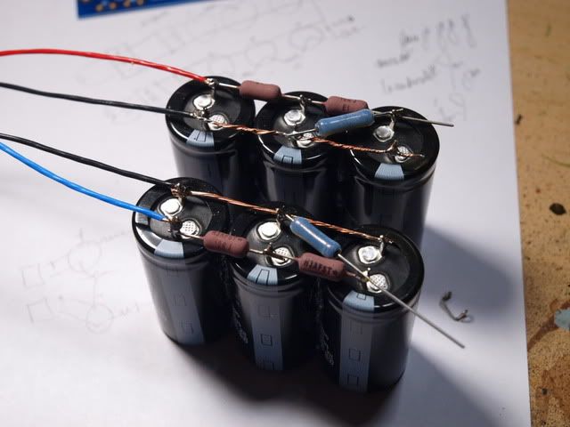
Anyway, the 50v 6800uf caps were chosen because they were at a 'sweet spot' on size vs. cost. You could use bigger or smaller if you like, but I would have at least 10,000uf (total) per rail.
10ohm 3W dropping resistors because I had some as well, and I needed to start somewhere.
The .22uf snubber cap was a suggestion from Wayne, he did a bunch of testing and found that value to give the most benefit in a single cap. 2.2k 3W was chosen as a bleeder because (yep, you guessed it…) I had them on hand - that value is used as a bleeder in Pass power amps.
Now after all that, I must digress at this point and say that all this is necessary because I'm using the transformer with the excess voltage. If you didn't have anything in your box and needed to order a new transformer, something like this would be appropriate --
Antek - AS-0522
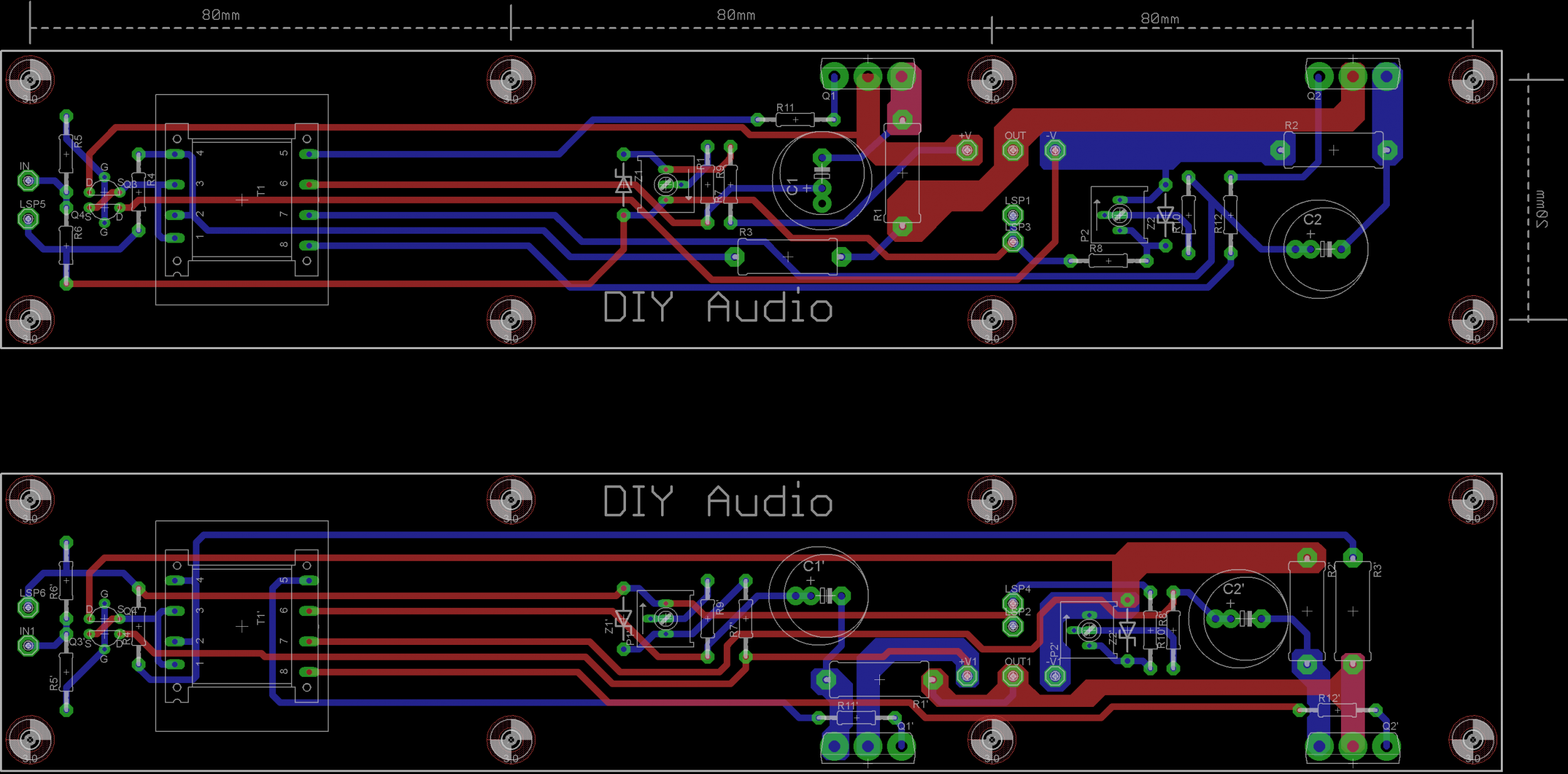
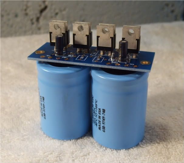
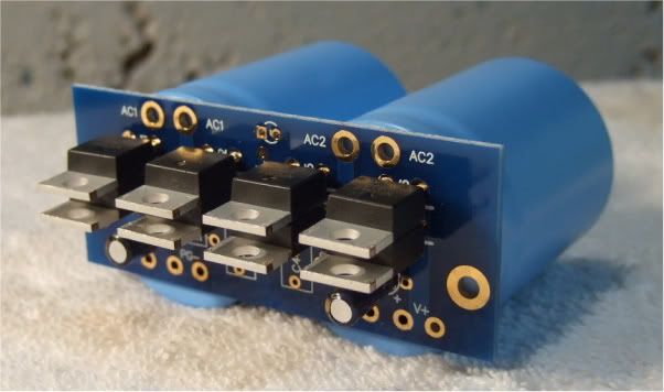
Also, you actually are able to mount big 'snap-in' style caps (10mm lead spacing) to the Peter Daniel board - like so;
These are 10,000uf 50v caps, BTW.
Cool! And it also could be mounted in a much smaller case if that is your style.
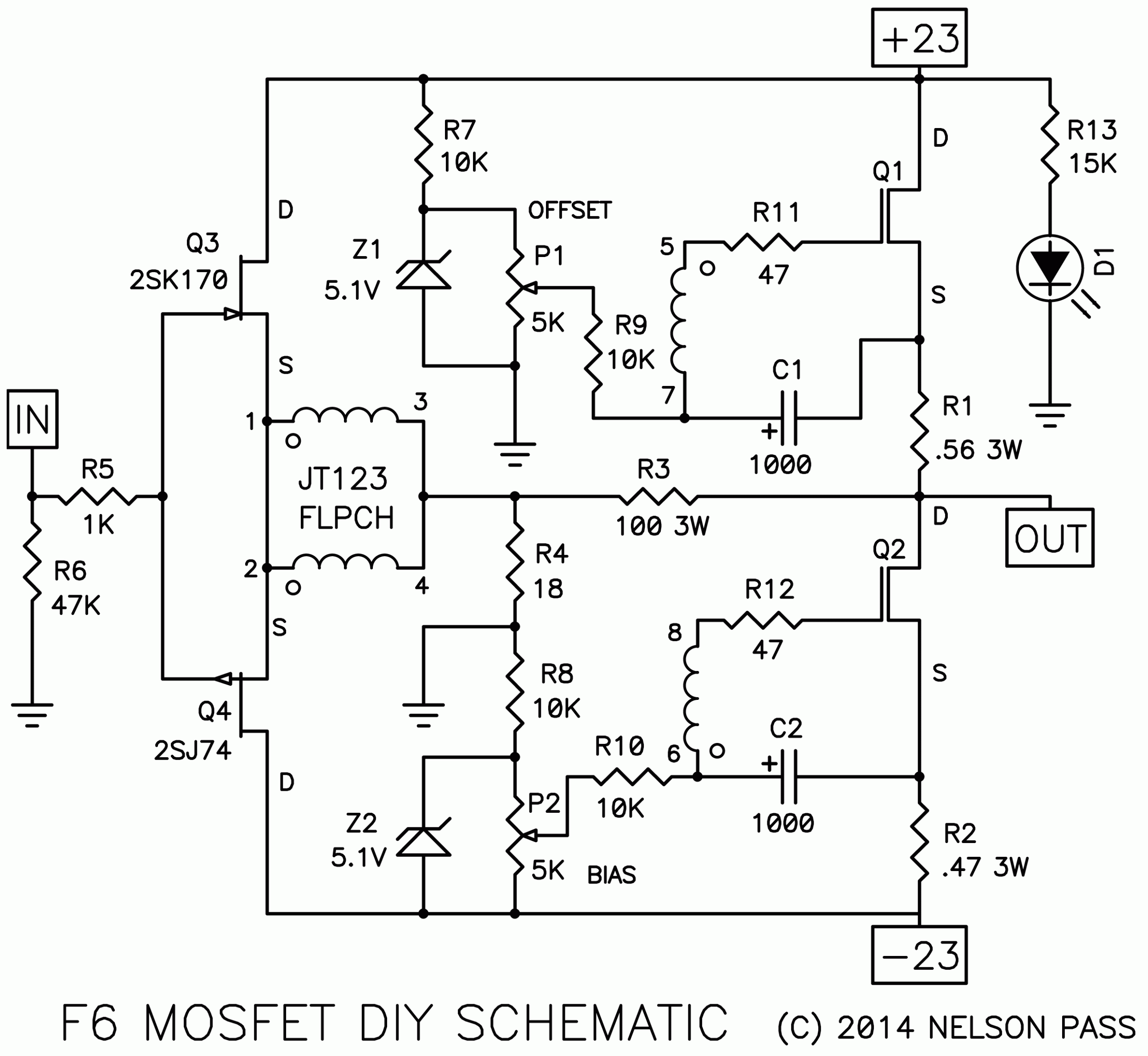
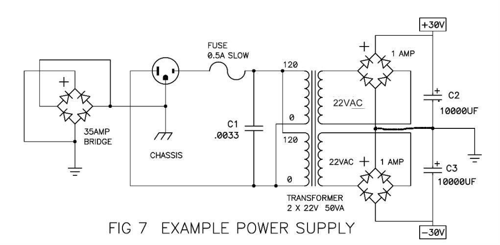
For reference, here is the schematic of the original schematic posted in the project.
Anyway, back to our regularly scheduled program.
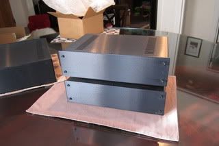
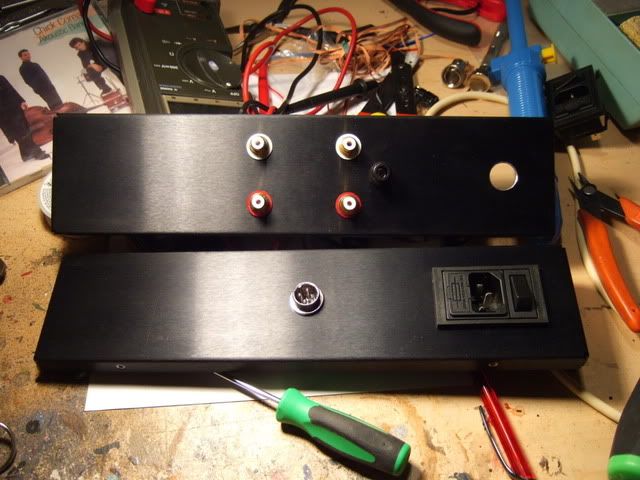
I ordered a pair of Par-metal chassis for this build, model 20-12083B website here -
Par-Metal (12"x8"x3")
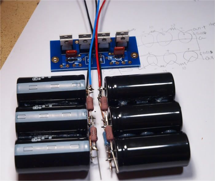
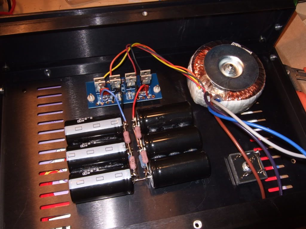
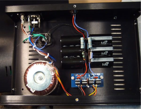
The PSU going together -
The rectifier board is from Peter Daniel (Audiosector.com) and was actually from a gainclone board. It's compact and very well designed. A LED will be added to it later.
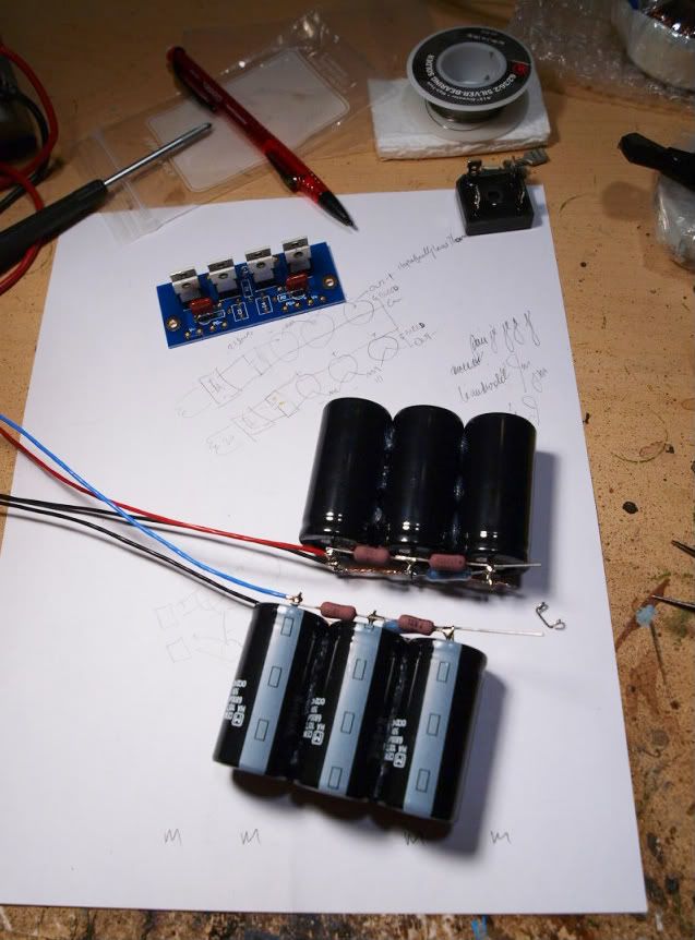
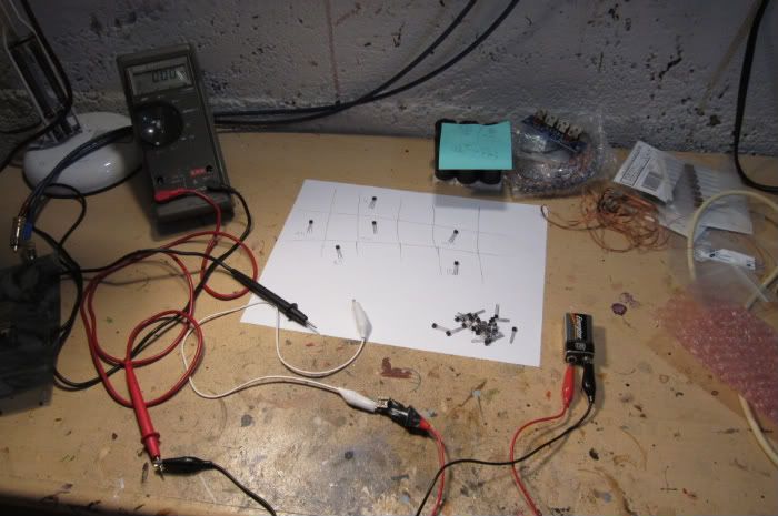
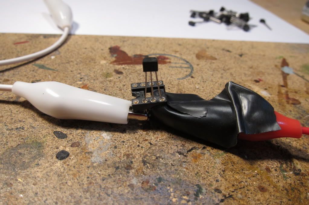
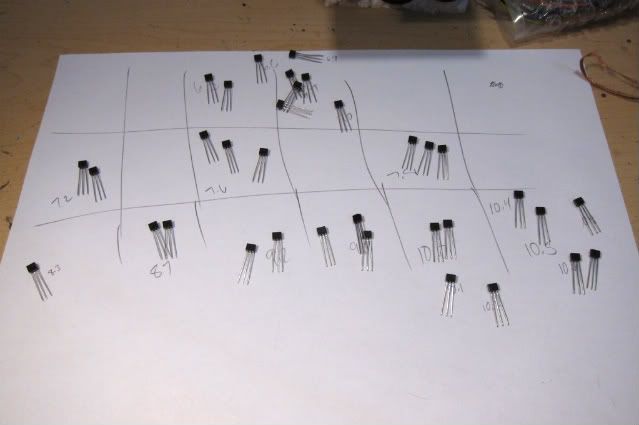
Now I got a pair of empty boards, without the matched jets like you get when you buy from PassDIY. So I needed to match the Jfets for Idss. Here is a good reference article -
Transistor matching
It's simple - a 9v battery, DMM set to MA, a couple of clip leads and the Jfets.
Here is the assembly of the PSU enclosure --
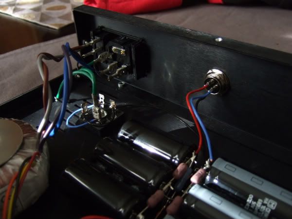
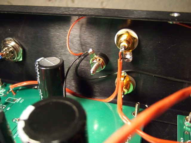
And this photo shows the wiring around the power entry module and the ground breaker-
The connections from chassis to earth to ground are exactly is drawn in the schematic.
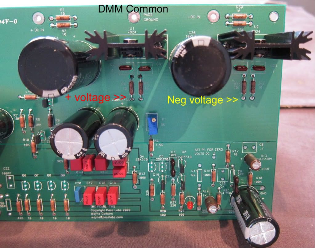
As I'm looking through my photos, I realize that I have no photos of the board being stuffed. (Then again, stuffing a board isn't all that exciting…) But I did need to take a photo to show where you place DMM leads to test the rail voltage.
One thing this photo does show is that although I have all the resistors installed, I don't have a jumper in the R15 spot. So, just in case you didn't see it in the article, (and I most certainly didn't see it either…) you need to put a jumper in R15.
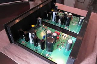
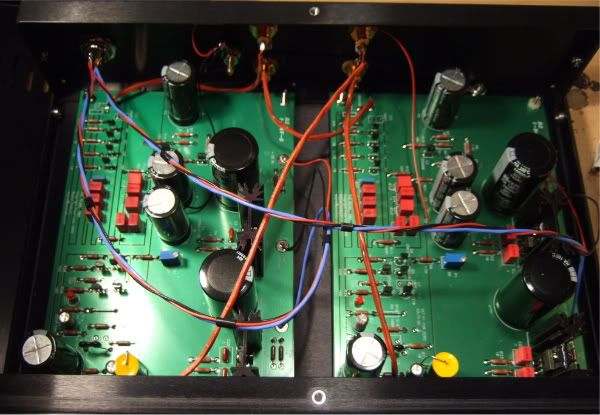
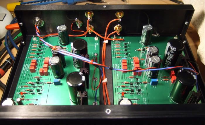
So by this point I'm getting down to final assembly, the boards are mounted, the RCA's and other connections are in the chassis and it all need to be wired together.
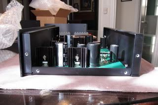
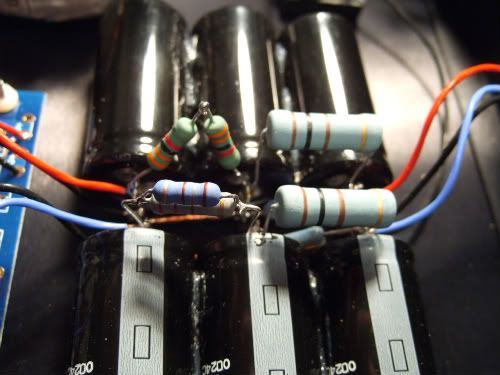
One problem, the unregulated DC from the CRCRC filter is +/- 47v. That's too much to put into the regulators.
The original 10ohm resistors in the CRCRC filter were obviously not enough resistance to reduce the voltage, so I reached into my somewhat meager supply of high-wattage resistors and kludged up this -
Now the eagle-eyed of you will notice that they are not symmetrical... and that is because the (+) rail draws more current than the (-) And all I was trying to do was get the voltage at the input of the regulators somewhere between 40 and 29. Fewer than 40v as that is the maximum the 7*24 regulators can have on the input, and at least 29 because the regulators need at least 5v more than the output in order to regulate properly. They are now about 31v.
Here is the entire power supply, the power entry module has a switch and fuse, you can see the 35amp bridge isolating the PSU ground from the safety earth, the toroid, rectifier board with snubber and LED, then the CRCRC filter.
The output from the PSU, positive, negative and ground are isolated from the chassis. The umbilical is just a 3-conductor cable.
Just for reference, here is a photo of the backs of the enclosures -
The guy that I had do some machining for me screwed up the RIAA enclosure and did it upside-down.
😱 In the grand scheme of things this is not a big deal, but it did mess up my wiring, specifically where the power cable got routed. The original plan was for it to be on the other side, and the power cable about 1/2 the length that it wound up being.
Now this rat's nest is not the final wiring, but it is quiet. Very quiet. I will get around to a nicer looking routing in the near future.
Here is a quick overview of how it's grounded;
Safety Earth - only connected to the primary side of the PSU and PSU chassis.
V+, V-, Vgnd floating in both chassis.
Input and output RCA jacks floating.
Ground lug connect to chassis.
PCB starground, (a lonely, unlabeled hole under C4 and above C12) connect to ground lug.
And then the lug is connected to the chassis, I just used a longer screw in the pem nut, a tab and a metal nut to insure good conductivity.
So by this point all I needed to do was clean up the wiring.
Wiring after the clean-up. It looks better and is quieter. Awesome!! The trick is to get everything routed as close to the chassis as possible.
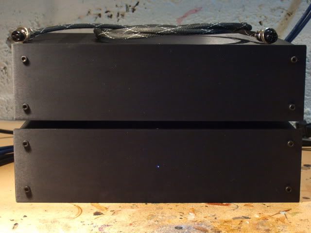
The stealth blue power indicator.
😀 😀 😀 On top is the umbilical.
There is a place for an LED and dropping resistor on the PSU board, and the 'light' is nothing more than an extremely small hole (>1mm) drilled in the faceplate and the LED pointing towards it. You need to look for the hole when it's off.
🙂 In the future I will probably have some CNC engraving done on the faceplates. But I do like the unassuming look of all black...
The umbilical is a 3-conductor wire from the surplus store, sheathed in techflex and terminated with '4-pin microphone connectors' from RadioShack
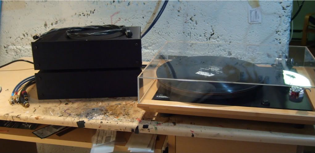
The completed Pearl 2. Shown with Turntable for scale.
This build is complete, it sounds fantastic and is astoundingly quiet. This is the first project I have done in a long time that was quiet (specifically PSU hum and radiant hum) from the very beginning I'm very happy with the results.
Now I need to sell off some of my random excess gear and buy a Shelter 501 cartridge...
🙂 🙂 🙂
A very special thanks to Wayne making this project available to the DIY community, and also to my buddy in California who sent me a few important parts to get this project completed. (You know who you are.)
🙂
Mouser cart for the Pearl 2 PCBs - Thank you avdesignguru!

Note: BOM does not include C7, any R20 input loading resistors or any additional input loading capacitors.
Power supply is a separate BOM that would be based on builder's preferred design.
Mouser Electronics


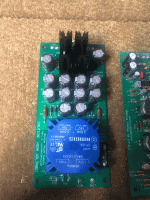


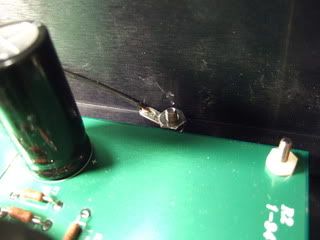
 I've included a photo of the backside of the potentiometer. I really hope anyone can help me with this
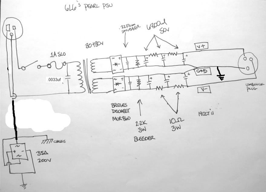


