Upgrade Micromega Solo cd player to top transport

Hi

Recently I bought a Micromega Solo CD player to use as a transport.

Just thinking if it’s good to diy some simple conversion to a pure transport.

My thoughts include both internal processing and external aesthetics…

1) take out all unnecessary analogue part of the circuit
2) change all wires to pure silver wires
3) change the power and output transformers to higher quality ones
4) install a hdmi i2s output
5) replace the acrylic cover with a gorilla glass one
6) diy a lighter clamp

Welcome any comments and advice.

Many thanks


Best regards

Class D amp with 300v mosfets

Class D amp with si8244 and 300v mosfets

I have made a stereo class D amplifier, which I intend to feed it with +/- 136v for the 4 ohm output load, Fsw=250khz xtal clock. The feedback is taken after the LC output filter, which consists of a 40uh coil and a 1.5uF capacitor, with a zobbel and a notch at Fsw.

An externally hosted image should be here but it was not working when we last tested it.


I used the ipp410n30 mosfet and the si8244 driver. The technical data are attached:
IPP410N30N - Infineon Technologies
https://www.silabs.com/documents/public/data-sheets/Si824x.pdf

For the test, I used a power supply of +/- 50v with a 200VA transformer.
With ipp410n30, I set the dead time to 45ns and I used a group of 22 ohms in parallel with a diode in the grile of each mosfet. I used a 5 ohm snubber with 660pf for good damping. I finded these values following the same recipe described by Chocoholic in the following threads, but i did not get such good measurements in the hardswitching mode, especially connecting the 4 ohm load to -vcc (if the load is connected to + vcc, the spike does not appear as large):
http://www.diyaudio.com/forums/class-d/224052-systemd_2kw-design-6.html#post3379820
http://www.diyaudio.com/forums/class-d/221498-system_d_md-class-chocolate.html#post3220098
http://www.diyaudio.com/forums/class-d/255046-systemd-liteamp-8.html#post4408076

I would like some suggestions on this spike.

Otherwise, the amplifier works very well, I will show you a few measurements in the following order:

1-residual at output, Fsw=250khz, some glitch, but it's pretty clean

An externally hosted image should be here but it was not working when we last tested it.


2-low side mosfet off, idle

An externally hosted image should be here but it was not working when we last tested it.


3-low side mosfet on, idle

An externally hosted image should be here but it was not working when we last tested it.


4-low side mosfet on, 4r load connected to +vcc

An externally hosted image should be here but it was not working when we last tested it.


5-low side mosfet on, 4r load connected to -vcc

An externally hosted image should be here but it was not working when we last tested it.


6-low side mosfet off, 4r load connected to +vcc

An externally hosted image should be here but it was not working when we last tested it.


7-low side mosfet off, 4r load connected to -vcc

An externally hosted image should be here but it was not working when we last tested it.


8-sine 50hz 4r load

An externally hosted image should be here but it was not working when we last tested it.


9-sine 1khz 4r load

An externally hosted image should be here but it was not working when we last tested it.


10-sine 10khz (some distorsions) 4r load

An externally hosted image should be here but it was not working when we last tested it.


11-sine 10khz before distorsions 4r load

An externally hosted image should be here but it was not working when we last tested it.


12-square 1khz 4r load

An externally hosted image should be here but it was not working when we last tested it.


13-square 1khz no load

An externally hosted image should be here but it was not working when we last tested it.


14-square 10khz 4r load

An externally hosted image should be here but it was not working when we last tested it.


15-square 10khz no load

An externally hosted image should be here but it was not working when we last tested it.

Yaqin MC-10l

Today I received the this amplifier and I had a small problem concerning to the sound.

I'm using the same speakers which are eminence alpha 12 and motorola piezo tweeters with 40 years old philips midrage and crossovers.

When I'm comparing the sound between a Fisher amplifier with 5 band equalizer. The midrange and the treble of the yaqin is nicer but the bass seems to be flat compared to the fisher amplifier.

What can I do to improve this valve amplifier. The valves are factory default that are provided from the factory.

Thanks Alot and Best Regards

Marantz CD74 repair advice

I have a Marantz CD74 bought off ebay to repair. It powers up, the laser arm moves, and laser has red light emit and focus action. The display and tray loading mechanism also works, but if I put in a CD, the turntable motor does not spin. I've done basic troubleshooting, checked power supply section voltage and servo MCU clock, and they are all fine. Just got the service manual but seems the turntable amplifier circuit is pretty complicated. Any advice where to start?

PA1 Tube Microphone Preamp Build Issues

I found a circuit for a mic pre submitted as an "Instructional" on the interwebs and decided to build it. It wasn't problematic or complicated and I've checked my work several times, and it works, but the waveform degrades at about 1400 Hrtz. At about a 1000 Hrtz, it shows 2000 on the oscilloscope and as the frequency I feed it decreases, the waveform falls apart while the scopes reading increases. Above 1400 Hrtz it's a good solid sine wave, very linear.
So I need help with that...
Also, if anyone could tell me after seeing the schematic, if I were to couple the DC voltage at the 12AT7's Plate, could I use an audio transformer like a Sowter 8230f? I wouldn't think it would have been built to be able to supply plate voltages and current. The transformer in use now is a single ended output transformer I had laying around. The project calls for a reverb driver transformer. I did not have one, but the idea is the same-ish (or is this my problem?). The project page is here: https://www.instructables.com/The-PA1-DIY-Tube-Preamp-Efficiently-Built-With-Sal/
Thanks for any help or advice.
PA1 Mic Preamp Schematic with Voltages.jpg

Bob Carver ”Transfer function duplication” applied to Loudspeakers with DSP?

Hi All

The other day I came to think of Bob Carver and his ”Transfer funktion duplication” as described in this Wikipedia article:

https://en.wikipedia.org/wiki/Bob_Carver se ”Amplifier Modeling”.

I wonder, if something similar could be transferred to Loudspeakers with DSP? I plan to build a pair of really big MEH´s for corner-placement, and will use DSP to manage crossover and EQ. But what target-curve/sound/coloring should I choose? That´s what I want this thread to be about. “Soundshaping”!

I think @wesayso has done some of what I am asking about with his line-array-speakers, duplicating some Altec-sound as heard at his neighbor, if I remember correctly.

So, what do you do and how? What makes a loudspeaker sound as it does? I know this is not simple, but much can be done with DSP!? And of course some things need to be done in the hardware like directivity, placement in the room …....

If there is an existing thread on this topic please let me know.

This is my first thread on diyaudio after many years of “recreational reading” and gathering of knowledge and ideas. I don´t have much to add my self as of now.

In curious expectation

Steffen

My Germanium based amplifier

You may have seen my past post about an amplifier based on Germanium devices. Well I've made further progress and modified the initial design which was found in a Russian forum. It was a nice learning experience along the way. I knew how transistors worked but never got into the details of how amplifiers were built around them. Originally the output transistors were soviet but an old Motorola data book led me to a good deal on set of 2N3616. Anyhow here's the original and then my version. Low frequency performance wasn't so great with a 2200uF output cap so it's been upped to 10,000uF. One observation seems to be that older devices tend to have higher distortion figures. Output power is 5-6 watts before clipping. Forgive me for any glaring mistakes :cheers:

Attachments

  • JLH-LH-Ge-AB-2.gif
    JLH-LH-Ge-AB-2.gif
    14.8 KB · Views: 562
  • Schematic_Export.png
    Schematic_Export.png
    36.4 KB · Views: 500

Where to get Fane 15-300TC

After some good results with the fane 12-250TC and the fact that I was impressed with a small fullrange bluetooth speaker I made I'm thinking to do a portable bluetooth speaker using the 15-300TC.
Problem is where can I find them..... it is still listed on the fane website but can't find any dealer who has them in stock.

any ideas?
I would love to try them. The 12-250TC was very impressive.

Best Regards
Jurgen

"Total Aural Dissonance" - the proper metric?

Cheever recommends a "figure of merit" -- Total Aural Dissonance -- achieved by a dynamic intermodulation measurement -- as being more consistent with what the ear actually hears (and creates due to the self-harmonics in the ear.)

I read Cheever's Master's thesis (linked as a 1 meg PDF here: http://w3.mit.edu/cheever/www/cheever_thesis.pdf and was wondering whether anyone on DIYAUDIO wants to offer a critique? Cheever lays the blame at high negative feedback, btw.

Pre-planning stage New big 3-way

A throwback to when I was 18 YO.
I'm finally going to use the Kicker EX124 drivers in a biggish box and a pair of SB mid-bass I bought off rabbitz; pre-Covid.
SB17MFC35-8
But I have a small problem here as my copy of Jeff Bagbys Passive XO and his Box Modeller no longer work.
Might take me a while tho as I have to clean up the shed first.
I read Jeffs posts [ RIP and sorely missed] about his Universal sub crossover and thinking that as I like to keep things as simple as possible I'd go with a first order electrical on the woofer as low as practicable.
But looking though my stash the only large value inductors I have are cheap laminate cored from Jaycar @ 9mH / 19AWG and a DCR of 1.9Ohms. I usually buy in pairs but I seem to have only one 5.6mH inductor there and that value was what I was going to use.
So I'm now wondering if I should make a true 3-Way crossing around 250/300Hz or simply going with a 2.5Way using a wide baffle and setting the woofer at the baffle step -3dB.Because I want a particular sound for Hard Rock I'll be using the venerable Vifa aluminium dome D26 tweeter and crossing somewhere around 2500/3000Hz.
I will be playing LOUD most of the time, these may live in the shed or be gifted to one of my kids later on.
Thoughts and prayers?

NAD 218 THX with dead channel

I pulled a NAD 218 THX amp from the local dump recently. One channel works beautifully, while the other is dead. On the dead (Left) side, one PS fuse was blown. Upon inserting a fuse from the working side (same fuse), the dead channel remained dead.

Schematics can be found in posts 7 and 8 here: AVforum.no - Nad 218 Thx reparasjon. It's pretty complicated to my eye since I don't often work with solid state devices. Plus there's the bridging, soft clipping, protection circuitry, balanced vs unbalanced inputs, etc. etc.

The blown fuse was F502, for V+ for the left channel in the first schematic. These are slow blow 6.3A fuses. V+ measures 72.9, whereas V- measures -73.1. Seems likely the PS is mostly working. I do notice, though, some burn marks around R704 on the PS board. It's a fusible resistor whose solder joints are shot, though it still measures 100R. That resistor is part of the V+ supply, though, so should affect both the L and R channels. I'll resolder or replace it, but hardly seems it could be the problem for the L channel.

Finally, the right side relay clicks on when the amp is turned on, but there's no relay click on the L side with fuse replaced.

Can anyone point to some next steps for me to check this thing out? I'd really like to get it going instead of parting it out - I can't see landfilling it as there are good parts there.

Subwoofer Crossover for Speaker Level Signal?

Probably this is a naive question, but is there a device like this Rolls SX95 but that takes a speaker level input signal rather than a line level input?
I want to use a subwoofer (non-powered, but yet to be built) with a pair of DML speakers using my old Sherwood 4109 receiver as the amp.
I'd like to be able to crossover from the sub to the DMLs around 100 Hz and have some independent control of the subwoofer output level. Having phase control and a few options for crossover frequency would be nice, but maybe not really necessary. Does such a device exist commercially? Could it be built cheaply?
Thanks,
Eric

https://www.amazon.com/ROLLS-SX95-A...ocphy=9007449&hvtargid=pla-663619777110&psc=1

Sealed Box Design for a Mid/Full-Range Driver

I'm adding a mid/upper range driver (Vifa TC9FD18-08) on top of a Transmission Line enclosure.
Obviously the TC9 will be in it's own sealed enclosure.
The TC9 has a Qts of 0.89.
This is outside the range of all of Vance Dickason's tables for sealed enclosures.
I've run it in WinISD with mixed success.
The first run was with the factory T/S parameters.
The second run was with someone's T/S parameters from their own testing.
I got dramatically different Vb's.
I also got high Qtc's (around 0.95).
Am I heading in the right direction, or can someone help with recommendations for how to design a sealed enclosure for a mid-range driver?

6N6P vs. 6N6P-I

guys - i am not smart here...
i have came accross two different version of 6N6P tube...
one is without "-I" and the other has its full name 6N6P-I.... it seems that the one with the "-I" is made to work in a impulse mode....

the question is this - can i use 6N6P-I the same way as 6N6P tube??... are they the same or are there any differences??... what are the differences??..... i don't get it....
thanks in advance.... many regards
daniel

datasheets...

6N6P-I
http://www.mif.pg.gda.pl/homepages/frank/sheets/112/6/6N6PI.pdf
http://www.mif.pg.gda.pl/homepages/frank/sheets/113/6/6N6PI.pdf
6N6P:
http://www.mif.pg.gda.pl/homepages/frank/sheets/113/6/6N6P.pdf

Sumo Andromeda mods

I've recently purchased an old Sumo andromeda power amp. Before i put it into everyday use, I thought i'd make sure it was all in tip-top condition first.

I'd like to replace all electrolytics, starting with the main filter caps.

They are currenly rated at a meagre 10,000uF/50v. From what I can tell, a 350wpc into 4ohm amp should have a little more than 20,000uF per channel.

I've been looking at whats available, and I can get either 12,000, 15,000 or 22,000 that will physically fit onto the original PCB.
Brands are either:
Elna LAO or BHC Audio (12,000)
Rubycon or Nippon (15,000)
BHC 'Audio' (22,000)

I'm baffled at to which I should go for, does anybody have any suggestions? What other items should I look into upgrading while i'm there?

Sorry about the large images.
2949351255_cec0c7e85a_b.jpg

2950203294_cf13a3426d_o.jpg

Sumo Andromeda very early series schematics

Hi all. I did something a little dumb.

A customer sent me a Sumo Andromeda that had failed.

A couple of previous questionable repair jobs, mix and match outputs....a lot of BS.

I stripped it down and the customer had a very nice copy of the early schematic. Well upon re-assembly, the board has holes ( and HAD components for ) C5, C6, and C7......if you look on the schematic, C7 is there but C5 and C6 are nowhere to be found !!!!.....DOH !

Does anyone have a very early schematic for one of these ?. The Sn is 400945 and it is a "mark 1" or "series 1" first run Andromeda.

It's ready to go except for those parts !

Thanks

Rob

Which Amp for my Subwoofer?

good afternoon,

I'd like to build a new amp for my subwoofer (Mivoc AW 3000, 12", 4 Ohm > datasheet in 50l sealed). The linked speaker will be replaced by an other 12" ( maybe a Dayton RSS315HF-4 > datasheet ) with better specs, sooner or later. Atm the Mivoc is driven by 2x TDA7293 @ +/- 33V in parallel configuration. This combination isn't really bad at all, I like it, but you know, it has always to be more ( & more & more ... 😉 ).

A new 500VA toroid will be ordered, but the voltage depends on what amp I choose.
First I've been thinking about a triple parallel TDA7293. A class D ( TDA8954, TPA3255, IRS2092? ) couldn't be bad either, but which one would be best for delivering current (buckets of it). Or how about a solid state Mosfet-Amp with IRFP240/ IRFP9140?
A woofer with a double 4 Ohm voice coil like the Dayton RSS315HO-44 ( datasheet ) driven in BTL with two amps seems also interesting to me.

So, what would you do?

best regards
Jochen

Critique my Outer Foil Determination Process

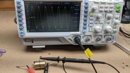
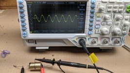
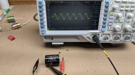
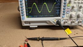
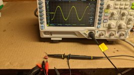
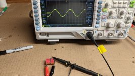
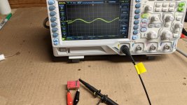
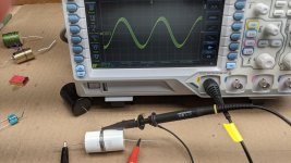
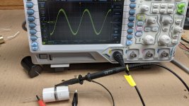
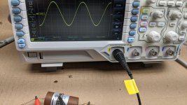
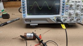
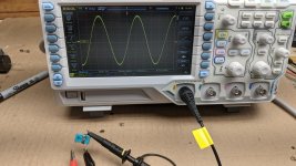
I was struggling with how to determine the outer foil on some caps and after trying a number of different techniques such as squeezing the cap, placing over a piece of energized lamp cord (120V 60Hz) and an article in this months Nuts and Volts magazine without clear cut results, I tried something else.
Wrapping a length of soft wire around the cap, hooking my oscilloscope to that wire and sending a 10 kHz signal through the cap and observing the sine wave was pretty enlightening when the signal generator leads were switched. Wrapping three to four times around the cap led to unambiguous results except for the blue/green rectangular Kemet which did show a very small difference.
See pictures for some of the results.

Obliggato 0.47uf
PXL_20220809_132208694.jpg PXL_20220809_132146822.jpg

Mundorf 1.0uf
PXL_20220809_183257307.jpg PXL_20220809_183225156.jpg

Panasonic 0.033uf (I think)
PXL_20220808_212323988.jpg PXL_20220808_212452443.jpg

Wima 0.022uf
PXL_20220809_000136480.jpg PXL_20220809_000019780.jpg

CDE 1.0uf
PXL_20220809_183914233.jpg PXL_20220809_183933025.jpg

Miflex 0.1uf (Outer foil marked by black line)
PXL_20220809_193206744 (1).jpg PXL_20220809_193126533 (1).jpg

Kemet 0.033uf (no significant difference)
PXL_20220809_192632157.jpg PXL_20220809_192701251.jpg

Thoughts or criticisms welcome.
  • Like
Reactions: JMFahey

Isolating Paradigm Reference Studio 100s (w/Hockey Pucks)

I thought I would post the results of my attempts to achieve better sound from the Paradigm Reference Studio 100 v.2 multi-way floor-standers (1 tweeter, 1 4" mid, 2 8" woofers -- 110lbs) that I bought a few months ago. They are located in my living room, which is 20'L x 12'W x 8'H and has suspended hardwood floors. I listen across the width of the room, so the range is pretty close.

In this particular room, the speakers have a very prominent bass output that, at higher volumes, can overwhelm the mids and highs, and also transfer mechanical vibrations into the structure of the house, producing very undesirable sound artifacts and killing the sound stage and imaging. This was especially true when I first got the speakers home and used the round brass feet that were screwed tightly to the bottom of the cabinets and placed directly on the floor. Loosening the feet a little did not really help.

My next step was to remove the brass feet and place small aluminum receiving cups under the spikes, which resulted in a *drastic* improvement in clarity, instrument separation, and imaging. I was really taken aback at how much improvement came from that simple change. I then decided to take it further by affixing self-adhesive plastic Magic Sliders under the cups, which improved the sound even more.

Still, at louder (but not ear-shattering) volumes, there was a tendency for the bass output to overwhelm the mids and highs coming from the speaker itself, as well as for mechanical vibrations to turn my living room into a giant subwoofer. So I decided some dampening material might help to minimize energy transfer and also clean up/balance the sound coming from the drivers. I figured the vulcanized rubber that hockey pucks are made of might do the trick, while the reduced friction of furniture sliders attached to the bottom would allow lateral vibration to occur and minimize transfer of mechanical energy into the hardwood floor. It $1 a puck, it could also be done at much lower cost than the beryllium/titanium/plutonium/unobtanium products marketed to audiophiles at great expense.

You would NOT BELIEVE how difficult it is to find hockey pucks in Oklahoma.

At first, I simply cut some furniture sliding felt to fit the pucks, removed the spikes from under the speakers, and placed the speakers on top of the pucks. Bass dominance of the sound output and mechanical transfer were drastically reduced, but clarity, instrument separation, and soundstage suffered woefully.

puck-felt by jeffdrouin, on Flickr

pucks-speaker by jeffdrouin, on Flickr

I then hypothesized that more lateral movement was necessary for allowing mechanical energy to dissipate out of the speaker enclosures, which could be achieved by reintroducing the spikes and placing the receiving cups inside the pucks.

So I bought a 1" forstner drill bit, found the center of each puck by inscribing a rectangle and drawing diagonals across its corners, and then drilled down 1/4" (the thickness of the cups). I inserted the cups, reinserted the spikes, and put them in place on the assembly.

puck-cutting by jeffdrouin, on Flickr

puck-cup-assembly by jeffdrouin, on Flickr

puck-cups-spikes by jeffdrouin, on Flickr

room-setup by jeffdrouin, on Flickr

(also visible in these pictures are my DIY speaker cables and interconnects)

The result is a *MUCH* more balanced and accurate bass response, with clarity restored to the midrange and highs, soundstage as good as I'd had it before, and almost no reverberation from the structure of the house.

Still, I can't help thinking that there might be too much volume taken out of the upper bass and highs. I'll do an A/B comparison with cups/furniture sliders alone, just to see if this is a placebo effect.

Now I'm thinking an even better solution might be to use less absorptive material in the feet and place them on a dense surface between the feet and the floor. Might try going back to cups/sliders -- but on top of granite slabs with a layer of cut doormat or something between them and the floor.

Frankly, the speakers are probably just too large for the room and engineering of the house, so I've been considering a switch to DIY full-range folded horns and a tube amp. But these changes have greatly increased the enjoyment of the music and system that I have. Any new steps will have to wait until we decide whether we're moving or renovating, either one of which will happen within the year.

Also, if anyone has further advice on room placement, dampening, or isolation, I'd really appreciate it!

Thanks, and I hope this documentation is helpful to anyone with large multi-ways looking to get better sound in their small rooms.
  • Like
Reactions: NBPK402

LCR fp ca au caps, any good

Hi And thanks for reading.
I purchased several ampohm polypropylene caps from cpc / farnell for use in a 3-way speaker, and instead for some reason they sent me lcr fp-ca-au caps.
The lcr caps are not the ones i ordered, but they do look similar to the ampohm.
I've tried out the lcr's and am underwhelmed to the say the least, boring sound with rolled off highs.
Have you heard anything at all about the lcr's, should i keep them or return them. Any opinions?
Film caps are not supposed to need any burn in time, or am i wrong there.
Many thanks.

Dual TDA1541 balanced output

I have started some breadboard tests for a fully balanced TDA1541 DAC.

finished Receiverboard: CS8414

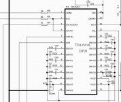
finished Board to split I2S signal into R + L (circuit see attachment)

Actually TDA1541 is configured in the usual way. (see attachment.)

output +/- for balanced should be AOR and AOL right?

Are my suggestions correct or has something to be changed?
How would be the I/V-restitor circuit?
2x30Ohm to ground for XLR?

Many thanks in advance for your support

Attachments

  • index.jpg
    index.jpg
    92.2 KB · Views: 462
  • tda1541.jpg
    tda1541.jpg
    35.8 KB · Views: 333

Why does Hornresp not display high frequencies??

Hi there,

I’m really confused about this.

I’ve attached a photo of a Hornresp power window. This is a simple sealed box using a woofer

According to the manufacturers specification, the driver responds approximately how I’ve marked over the photo.

Yet what Hornresp displays is as if a low pass filter is a applied. I’ve checked filter wizard and nothing is engaged.

what am I missing??
Thanks.

BA pre good... WLS2018, not so good

I know the reason is me, my misunderstanding but I cannot figure it out: why the Pass pre I built with the Burning Amp board works and works well no matter in which system I put it but my build of Waynes Line Stage makes a hidious noise in one system and is fine when used with a Pass (F6) amp and ordinary CD player.

I would think that it would be all or nothing, I made a mistake somewhere but that WLS is a gem in one systen and Seriously non-funtional in the other. While the BA pre is unflappable. Oh, to be fair the WLS uses output caps just like the BA... the DC offset was not tamable with just the pots so that difference is not a difference. I don't understand, what makes a preamp just a hidious noise maker only in some situations? Please, Help me understand!

Daphile - Unable to save settings of M-audio Audiophile 24/96 (PCI) sound card

I have the following three sound cards:
1. M-audio Fasttrack Pro (USB)
2. M-audio AP192K (PCI)
3. M-audio Audiophile 24/96 (PCI)

There is no issues when editing and applying settings for the first two devices via the web UI of Daphile. Here's an example of making changes to the settings of M-audio AP192K.

save 192k.jpg


When I tried to use the third one, error occurs. After applying changes to the M-audio Audiophile 24/96 for the first time, it appears that the change wasn't saved successfully as it shows the default settings identically. After applying changes for the second time, this device is disabled. I've tried Daphile versions from 19.xx to 21.xx both standard and rt editions, and they make no difference.

I took the initiative to dig deeper by ssh to the beta version of Daphile, and noticed that there is a directory named "/mnt/hdd/system/spac/M Audio Audiophile 24/96/" created by default and storing all kinds of settings for my third sound card. When I tried to save some changes of this card via the web UI, a new directory named "/mnt/hdd/system/spac/96/“ was created and containing the newly-changed settings only. Therefore, the new settings couldn't be applied to the card, as the system shall always read settings from the default directory. Please refer to the following screenshots.

save 2496.jpg


It seems to me that the "/" symbol in the model name of this card is the cause of this issue, since the OS considers "/" as the indicator of a sub-directory, instead of a character within a model name.

My first reaction was to rename the device in Advanced Media Server Settings. It was successfully renamed there and remained as renamed, but this made no effects to the Audio Devices section. Please see the following screen shots.

rename 2496.jpg


I also tried to rename the directory "/mnt/hdd/system/spac/M Audio Audiophile 24/96/" to "/mnt/hdd/system/spac/M Audio Audiophile 2496/" and edited all the setting files under this directory containing "M Audio Audiophile 24\/96" to "M Audio Audiophile 2496", trying to avoid the "/" symbol problem. But it didn't work. The device name in the Settings web page remains "M Audio Audiophile 24/96" with the "/", and it still creates a new directory named "/mnt/hdd/system/spac/96/" to store changed settings while reading settings from "/mnt/hdd/system/spac/M Audio Audiophile 24/96/". Please refer to the right part of the second screenshot.

Next, I tried to find all files containing "24/96". The command couldn't fully finished. The following screenshot is the best I can get.

all2496.jpg


The darker parts are files inaccessible. The blue parts are Daphile's change logs. The normal parts includes some binary files and other devices with "24/96" in their model names maybe? The first lighter part is exactly where I tried to rename my M-audio sound card. I then probed into the second lighter part and result in the following screenshot.

proc.jpg


This is where I totally stucked. I don't know how to edit binary files on Daphile since there's no apt-get available in the system, nor how to make changes to the files in "/proc" directory. I don't even know whether it will solve the problem or not if the "/" between "24" and "96" is successfully removed. Anyone here can help out?

My wild guess is that this issue is universal to all audio devices with "/" symbol in their model names. Does anyone encountered similar problem of failing to save changes to the audio device settings?

Stale skills, quick proof of an Attentuator w/audio monitor out design?

Hi all..

My electronics schooling and day-to-day practice of it was all left behind a few careers and many years ago. Getting back into home audio repairs as a hobby again and am building up some of my test equipment. I recall having a handy amp loadbox back when I worked in a shop as a kid.. 4 and 8 ohm switchable input impedance with a volume controlled set of outputs on the back that we could hook a speaker into monitor the output while soak-testing an amp.

Component-wise Im figuring the load resistors will be 8ohm, 100w-ish, 100k 1w or similar and a 10k audio taper pot.

Am I out to lunch or any suggested changes?

thanks for any help you can offer.. Im waaayyy stale, haha.

load box.JPG

Ceramic 4-way 1st ORDER (bang for the buck)

Carbon Fiber 4-way 1st ORDER (bang for the buck)

Greetings members!

The weekend was productive Fellaz! I have revamped the system, It was slightly inferior, and I have made NEW MODELS
The next five pages of my posts in this thread will be OUTDATED. THIS VERSION IS NEWEST.
!!***CHECK THIS LINK FOR GRAPHS-VISUALS FIRST***!!
https://www.diyaudio.com/forums/multi-way/334161-ceramic-4-1st-bang-buck-6.html#post5709858

This idea has spawned an 3-way OFFSPRING, which also does it, with a COST, COMPLEXITY, and SIZE CUT by a FACTOR OF 2.
!!***https://www.diyaudio.com/forums/multi-way/334161-ceramic-4-1st-bang-buck-6.html#post5710001***!!

I have mapped all the drivers seperately, and then have combined them into a TRUE 1st order electrical 4-way response graph.

The reasons behind this is that I realised the crossover points between the drivers must be -6db to have a flat response, therefore I have made assymetric crossovers to make sure Im as flat as possible.

The tweeter is already modelled with the series LCR notch in parrallel to the driver, but I havent added the effect of the Zobel impedence equalization networks which are in parallel to the cone drivers.
Thier job is to make sure that the higher frequency zones after the low-pass points to the cone drivers are rolling off at least as intended, if not quicker (meaning 9/db octave instead of 6db/octave). This will even out the bumped kinks you see on the red midwoofer graph, and the black midrange graph past thier low pass points.

Here are the crossovers:


1). 1" TWEETER
39$ SB26CDC-4 3.4 OHM
SB Acoustics :: SB26CDC-C000-4

1st order high pass CROSSOVER VALUES (7200hz -0, 5400hz -3db, -3800hz -6db)
C1 = 8.66 uF

5.5$ KZK WHITE LINE MKP CAPACITOR (WILL USE 8.2uF)
0.5$ KZK K78-34 BYPASS CAPACITOR (WILL USE 0.02uf)

SERIES NOTCH FILTER PARALLEL TO TWEETER (inductor resistance value has been subtracted from resistor value)
C = 33.93 uF
L = 1.57 mH (0.375 OHM)
Rc = 5.69 Ohms (INDUCTOR RESISTANCE INCLUDED)


2). 3" MIDRANGE
39$ RF-30QY-PRO 7.4 OHM
GHXAMP 3 Inch Midrange Speakers 8ohm 30W Neodymium 92DB Mediant Loudspeaker For Car Audio Upgrade 3 way speakers 1PC -in Combination Speakers from Consumer Electronics on Aliexpress.com | Alibaba Group

1st order high/low pass CROSSOVER VALUES: (450hz -6db, 675hz -3db, 900hz -0db / 1800hz -0db, 2700hz -3db, 3600hz -6db)
C1 = 33.65 uF
L1 = 0.44 mH

13$ KZK WHITE LINE MKP CAPACITOR (WILL USE 33uF)
0.5$ KZK K78-34 BYPASS CAPACITOR (WILL USE 0.02uF)
8$ VAJD AUDIO 0,19 Ohm 1,6 mm AIRCORE COPPER INDUCTOR (WILL USE 0,44 mH)

INDEPENDENCE EQUALIZATION ZOBEL CIRCUIT:
C = 11.8 uF
Rc = 9.25 Ohms


3). 6" MIDWOOFER
44$ STX 180.8 FCX v2 6.2OHM
W.18.180.8.FCX_v2 - Nagłośnienie STX

1st order low pass CROSSOVER VALUES: (337hz -0db, 450hz -3db, -675hz -6db)
L1 = 2.19 mH

16$ Z52-2,2/1,5 TOROIDAL IRON POWDER INDUCTOR 0,11 ohm (WILL USE 2.2mH)

INDEPENDENCE EQUALIZATION ZOBEL CIRCUIT:
C = 4.05 uF
Rc = 8.75 Ohms

4). 10" WOOFER
82$ STX W.27.500.8 FCX 5.9OHM
W.27.500.8.FCX - Nagłośnienie STX

1st order low pass CROSSOVER VALUES: (66hz -0db, 100hz -3db, -133hz -6db)
L1 = 9.39 mH

20$ Z52-9,1/1,5 TOROIDAL IRON POWDER INDUCTOR 0,22 ohm (WILL USE 9.1mH)

INDEPENDENCE EQUALIZATION ZOBEL CIRCUIT:
C = 25.19 uF
Rc = 7.38 Ohms

(COSTS: tweeter setup- 90$ / PAIR CROSSED, midrange setup - 121$ / PAIR CROSSED, midwoofer setup - 120$ / PAIR CROSSED, woofer setup - 204$ / PAIR CROSSED)
TOTAL: 535$ + zobels, using JANTZEN SUPERES.
If I wont have enought money, I will build cabinets but I'll leave the woofers out for some time. I'll loose only the lowest octave.

738848d1551090668-ceramic-4-1st-bang-buck-system-acoustic-response-electrical-zobels-modelled-png

attachment.php

An easy MTM.

I’ve been playing with Wavecor WF160WA02s in various configurations for several years, while liking their sound however, never had great success in getting them to play really solid low lows. I wanted to do something with them, and recently decided that, as my HF hearing deteriorates (I’m in my late 60s), an MTM might give a better presentation for a deaf old coot…..

I had on old pair of 20L boxes which were suitable after some work with table saw & router, and Peerless XT25SC90-04 tweeters available (suitably small & perfect sensitivity), so after the requisite amount of caffeine, came up with these, using a Simple LR2 xover (2mH & 4uF on the series woofers, 11.3uF & 0.68mH on the tweeters).

The result: gave the desired forward projection, with a clean, clear, uncoloured & detailed sound. The sealed boxes modelled an F3 of ~80Hz, but I was impressed by the low mid-bass.

My next challenge is to decide what woofers to pair them with, currently sitting on top of SEAS CA18RLY ( a gem of a speaker), but will probably go with a pair of 6” Jaycar Polypropylene woofers (from the days when they sold good drivers) which I know could do well. Also looking at the SB 6” & 8” PFC woofers, but spending $$ is against my wont, specially when I have so many unused drivers in the workshop...

Attachments

  • MTMs.jpg
    MTMs.jpg
    639.4 KB · Views: 118
  • Like
Reactions: GM

Tape deck maintenance & What are some good performing compact cassettes (type 1,2 & 4) that are affordable and easily available in packs these days?

I've just recently picked up a Rotel RD-960BX for only $70 locally. It isn't in the best of shape and I guess the guy wanted a quick sale. But only a broken rwd button, and the VFDs internal cover is drooping - glue has gone soft and melted. It also really needed a good clean on the tape transport. I'm yet to make a demagnetiser, and i'd like to clean and lubricate the drive system. Belts seem ok, but might replace anyway. Pinch roller has probably gone hard too... though not sure where I can source parts. There is one listing on ebay but price is kinda ridiculous. Webspareparts doesn't seem to have anything specific either. I think the machine might need proper calibration... but not sure. But it seems maybe the right channel is recording a bit weak. Could this be a head alignment issue? Or maybe internal trim pot needs adjusting? Or maybe some capacitors need replacing?

Also, looking for a few good performing tape recommendations that won't send me broke. (After seeing ebay prices).
I've so far tried new Maxell UR (bought 10x), but I don't think I can recreate the results shown in Cassette Comback's videos... Though his decks are much better than mine. I've found that I needed to max out the bias at -20% when using tones generated in Audacity. I've also found it easily distorts at/over +3db. High frequency tones at 8kHz sound quite bad to the ear as well. When recording and listening to music, treble sounds quite muffled, bass distorts easily and muffles all other sounds. Sounds kind of like I have my head in a bucket of water lol... but I guess I can't expect much from a cheap and dirty type 1 ferric. Maybe I'll upload a recording if anyone's interested. I recorded the music with dolby C, which works great for removing hiss, but i'm not sure if it's helping the signal at peak loudness. Is it better to record without dolby and just live with the hiss?

10 days ago I spend $40 on 2x new TDK CDing2, so should show up in the mail soon. So i'm interested to test those, but they weren't cheap. I also slapped down $50 on ebay for a new 1994 TDK MA-110 but I'm not brave enough to open it yet lol. It should be fine for one off testing/tinkering, but at those prices, it's not really affordable even just for a small handful for my favourite music. So i'll definitely need help looking for affordable alternatives. I'm not sure if buy used is any good, but I don't want to waste money on mint unopened collectors items, especially if I'm going to open them lol. I'm also not really that interested to 80s vintage stuff either. I'll leave that for the collectors to enjoy.

Thanks 🙂

Measuring headphone frequency response... And/Or have I lost my youthful hearing?

So i received a free set of headphones with a parcel today. On the back I noticed its frequency response spec on the back (20-10kHz) So I thought i'd try to see if i could test and confirm those specs, which i could. Though I was a little bit surprised with what I found.
  1. First, it turned out that I had the wrong settings on my computer which limited the output to 23kHz, so that was rectified.
  2. It turns out that even if its frequency response was only up to 10kHz, I could still measure output up to 40kHz.
  3. Understanding that the 10kHz earphone spec is where output volume begins to drops, not where it fades to zero. (Measured as 13.3kHz first try and dropped to 10kHz on subsequent tests)
  4. After testing the over ear sennheisers a few more times, it seems i'm getting drop outs. I wonder if doing these tests is damaging my DAC, headphones and/or mic....?
  5. So it may still be possible that I haven't lost my precious young high frequency hearing just yet? And perhaps maybe it's just the limit of my old headphones or is the limit of my old DAC?
The headphones I tested are:
Maxell MHP-EP02 (in ear) (10kHz spec, 13 to 10kHz measured)
Sennheiser HD429 (over ear) (22kHz spec, 9kHz measured)
Sennheiser CX 3.00 (in ear) (21kHz spec, 16kHz measured)

Thoughts?

Attachments

  • 3x headphones test.png
    3x headphones test.png
    423.6 KB · Views: 159
  • 3x headphones retest 2.png
    3x headphones retest 2.png
    533.5 KB · Views: 148
  • Maxell MHP-EP02 (in ear) Freqency Response 13kHz.png
    Maxell MHP-EP02 (in ear) Freqency Response 13kHz.png
    10.4 KB · Views: 131
  • Sennheiser CX 3.00 (in ear) Freqency Response 16kHz.png
    Sennheiser CX 3.00 (in ear) Freqency Response 16kHz.png
    10.1 KB · Views: 139
  • Sennheiser HD429 (Over ear) Freqency Response 9kHz.png
    Sennheiser HD429 (Over ear) Freqency Response 9kHz.png
    10.4 KB · Views: 144

FREE: Bourns 300k Pro Audio Potentiometers

Oooooold stock. I have probably 10,000 of these. If you're local -- come and get 'em! Carlsbad, California. These are a custom run of 300k ones from when I did contract engineering work for Ultra Stereo Labs in San Luis Obispo.

Here's a Digi-Key link to the 50k ones.
Here's a Bourns link to the datasheet.

Bourns300kPot001.jpg

Bourns300kPot002.jpg

20220618_140931.jpg

Bourns Pro Audio Digi-Key.JPG


Not too keen on shipping these. Time is my most scarce commodity lately. Maybe in a couple weeks...

Cheers, -Casey

using isolated power supply for a Head preamplifier

Hello,

I have a Lyrec Fred reel2reel tape recorder with a noisy head preamplifier , noise is picked up by the digital circuits that controls the tape transport (sounds like a very week "modem audio" like sound) . The design is like this from the factory since this recorder is intended for editing (tape splicing, no recording is possible) . The preamplifier is using NE5534 which is quite good , what options do I have to filter out the digital noise from the digital ciruits? should I use an isolated power supply for the preamplifier to isolate the didgtal ground ? attached is schematics of the preamplifier and the entire schematics of the unit
Thanks

Attachments

Updating a classic: BUF634A

http://www.ti.com/product/BUF634A

We've put a preliminary datasheet and prototype samples up on ti.com for a refresh of the classic BUF634. The new device is called BUF634A, and will be available first in the SOIC package (same pinout as the original), with other packages following afterwards.

A few notes on how BUF634A compares to the original device:
-Wider bandwidth: 210 MHz in full bandwidth mode, compared to 180 MHz
-Lower power consumption: 8 mA vs 15mA in full bandwidth mode
-Higher slew rate: 3750 V/us vs 2000 V/us

We've also made a new evaluation board for the new device, and it is designed specifically for customers to try different composite amplifier combinations with the BUF634A. There is a footprint on the PCB for the dual op amp of your choice (SOIC package), as well as RCA input connectors and a headphone jack at the output.

http://www.ti.com/tool/buf634adevm

We're a couple months away from the full release, but I thought there would be interest here in the preview information and proto samples. Enjoy!

Super long adapter for Horn so as to create time delay?

Good day.

I was wondering if it was possible to use a super long horn adapter (lets say 1 to 2 meters long) so as to create a delay. Kind of like a horn instrument (french horn) where the diameter of the horn is basically the same for most of its length until the end. How would this affect the response, this extra 1 or 2 meters. The idea would be to use a compression driver that goes from 1k to 15khz.

Thanks,

DML advancing

Been interested in Distributed mode loudspeakerdrsign DML. Have one 40 watt Dayton excitor and have had fun experimenting with different designs and materials. Just watched a YouTube video called hybrid DML. 4 part build with excellent test result graghs , even all important spectral decay graphs. It was designed rbased on the commercialy available AER Goldie speaker with optional sub woofer. They use acrylic panels with one excitor. Not very large think 600x400 mm 3mm thick copy AER is 2mm I think site noted forgot price? The homemade one is super easy to build and it tested really well for how rediculus the entire project cost. I'm just going to copy the design since I have no test equipment. Will post results of how they sound. Michael

Permeability and shielding materials

I want to pick up some kind of ferrous sheet material for general purpose shielding. Mu metal or permalloy sheets are crazy expensive, small and few suppliers. Carbon steel is cheap but not the best shield (too much carbon). Wrought iron is an excellent shield highly permeable, 100% iron, no carbon, but its not available in sheets. Then I came across this stuff, iron foil. Cheap, has anyone used it? I understand the idea is to redirect magnetic fields with a shield, as no material actually stops the field. But controlled redirection of a field getting near a sensitive input for example.

https://www.ebay.com/itm/372501495398


https://www.engineeringtoolbox.com/...eability Medium , 0.999834 21 more rows

Master Nagaoka Tetsuo explorations on matrixed single stereo speakers

Hello and how do you do !

A few years ago I presented the theory and operation of matrixed single stereo loudspeaker
http://www.diyaudio.com/forums/multi-way/200040-stereophonic-sound-single-loudspeaker.html


Just recently I discovered that late Nagaoka has left us with a huge heritage of single stereo matrix loudspeakers
ko.gif
ko.gif
ko.gif


Basically he used two kind of matrixes. For 3 and for 4 elements.

The 4 element matrix looks like this:
Notice that this is MS matrix. The front elements sum acoustically to form L+R signal.
matrix02.jpg

hkjunk0.web.fc2.com/hobby/audio/matrix_db/matrix02.jpg


And the 3 element matrix is like this:
We can see it is the famous x=0.5 matrix 😀 (Notice though the left amplifier channel negative terminal is left unconnected, possibly to avoid a ground loop?)
matrix03.jpg

hkjunk0.web.fc2.com/hobby/audio/matrix_db/matrix03.jpg


{HIRO}'s Website!! - matrix_db1


(edit: those hkjunk images are pain to see online, just copy the link to an empty window)
.

Attachments

  • matrix02.jpg
    matrix02.jpg
    25.3 KB · Views: 1,750
  • matrix03.jpg
    matrix03.jpg
    15.7 KB · Views: 1,862

VTL stereo 90/90, resistor value

Hi,

I have a VTL stereo 90/90 amp on my workbench with a dead right channel. As the faulty amp ran unattended for a longer time, it seems a lot of current has been flowing and there are two resistors on the PSU Board which are totally burned. The resistors are unique (i can't check the other channel for values). I have two different versions of Manley's VTL tube amp book, but they do not give any information about this special PSU. I already contacted VTL but they do not reply. Anyone can help - any owners of stereo 90/90 amp perhaps?

Kind regards, Michael

IMG_0005.JPG


IMG_0006.JPG

Sony TA-E86B Fault

I've come across a fault with my Ta-e86b where as at low volumes the right channel looses all low frequency and the channel goes out of phase with the left channel, pic of the scope traces attached, when the volume is turned up say 5db it corrects itself in volume and almost in phase, the fault? comes into play at volume control out.

Attachments

  • DS1Z_QuickPrint1.png
    DS1Z_QuickPrint1.png
    20.1 KB · Views: 212
  • Sony ta-e86 flat amp.png
    Sony ta-e86 flat amp.png
    281.4 KB · Views: 264

First Song

What is the first song that You like to play from a fledgling speaker project?
I'm not asking about the song that you might use to formally test the speakers but the one that you just want to hear. They may be one in the same but they don't have to be. Also the songs are going to change from day to day, project to project, and I understand this. I'm just looking for some fun answers and feed back.

Today I am going to fix some drivers into my current project and play Stranglehold , then most likely Iron Horse "Fire on the Mountain."

Stranglehold
Fire on the Mountain

Jeremy

Turn an old dead Tube Radio into powerful wireless speaker / Amplifier

Hi everyone.

Below I present you a great little project easy to make at home.

the project is based on a small dead tube radio made in the 1950s that I bought second-hand, the electronic card inside is completely destroyed and irreparable, but the facade of the radio and the aesthetics in general in good condition.

For all these reasons I decided to give new life to this radio by replacing all the dead electronics with a wireless amplifier card with the possibility of having wifi / bluetouth / usb connectivity and of course having the main possibility of playing internet radio station.

After some research I ordered the Up2Stream Amp V4 card which will allow me to have everything I want in the radio and with a very strong amplification of 100w based on a good quality digital amp.

This card’s power exceeds what I need to drive the internal loudspeaker of the radio that I have kept, but as noted in the title the project is more than a radio, it is also a werless hifi amplifier.

For that reason I installed a switch that will allow me to operate either the internal loudspeaker, or a powerful external loudspeaker to benefit from the high power of the card.

For this fact the card needs a good power supply that I made based on a 2*18v Ac 2A transformer, a 4700uf pro capacitor and a pair of powerful diodes.

On radio, I kept the internal loudspeaker, the on/off switch and the bindings post to connect an external speaker.

really after installing the card, the sound is really great and very transparent especially with my jbl 4628b pro speaker.

link To up2stream Amp Mono : https://www.arylic.com/products/up2stream-amp-mono-board

Attached some photos of the project, for more you can see the video of fabrication and many other projects on my youtube channel, here is the link of the video:
Login to view embedded media

Attachments

  • 20220615_120002.jpg
    20220615_120002.jpg
    392 KB · Views: 95
  • 20220616_211129.jpg
    20220616_211129.jpg
    323.9 KB · Views: 98
  • 20220616_211158.jpg
    20220616_211158.jpg
    406.5 KB · Views: 104
  • 20220626_125456.jpg
    20220626_125456.jpg
    197.4 KB · Views: 105
  • back.jpg
    back.jpg
    94.1 KB · Views: 106
  • IMG_364f1.jpg
    IMG_364f1.jpg
    164.3 KB · Views: 103
  • IMG_3641 (1).JPG
    IMG_3641 (1).JPG
    396.3 KB · Views: 104
  • IMG_3648.JPG
    IMG_3648.JPG
    231.7 KB · Views: 113
  • IMG_3657.JPG
    IMG_3657.JPG
    271.3 KB · Views: 102
  • IMG_3664.JPG
    IMG_3664.JPG
    384.8 KB · Views: 92
  • IMG_3706.JPG
    IMG_3706.JPG
    419.6 KB · Views: 100
  • Thank You
  • Like
Reactions: JMFahey and GM

Ground connections between two PCBs sharing signal and power

Hi!

I am designing a PCB with a LM1875 power amp, a linear power supply (transformer is not fitted on the board), and two regulators providing +/-15V for powering a preamplifier circuit on an other board.
I am gonna use a connector for signal input (from preamp PCB), and an other for +/-15V output (to preamp PCB).

What would be the best way to connect ground between those two PCBs please? One connector for signal and ground and the other one with +15V and -15V, or one with just signal and the other with +15V, GND, and -15V? Or maybe there is a better way?

I try to make the ground on the power amp PCB look as close as possible to a star ground.
The preamp board will have his own power filter capacitors, and decoupling capacitors on each ICs too.

Please apologize my bad english.
Thanks a lot for your help!

Looking for Ribbon (Foil Flex) Cable for Tonarms

After perform various listening tests with RCA cinch interconnect ribbon cables against usual coax cables I am surprised about the excellent sonic character of cables like this one under
https://ibex-audio.eu/sternklang
https://www.adverts.ie/cables/nordost-flat-line-gold-mkii-interconnects/2623840
https://positive-feedback.com/Issue64/mojo_interconnnects.htm
https://www.thecableco.com/clearview-excalibur-digital-ribbon-rca-digital-cable.html
https://shop.mapleshadestore.com/Clearview-Excalibur-Analog-Interconnects_p_1189.html
https://audiophilereview.com/cables/5-cable-combos-that-wont-break-the-bank/
https://www.bastanis.com/audio/cables/interlink-heartbeat
http://www.konus-audio.com/ephemera-interconnect-cable.html
https://www.solidcoreaudio.de/cinchkabel.html

I would be interested to know if this kind of cable connection also exists for tonearms (between cartridge and tonearm connector).
Maybe realized in the kind like VPI Industries, but instead twisted cable version a flex cable version.
Thanks for an advice.

Attachments

  • WD-VPI-Traveler.jpg
    WD-VPI-Traveler.jpg
    43.8 KB · Views: 144
  • vpi-traveler-v2-manual-turntable.jpg
    vpi-traveler-v2-manual-turntable.jpg
    47.6 KB · Views: 159
  • 1112vpitra.promo_.jpg
    1112vpitra.promo_.jpg
    18.8 KB · Views: 143
  • player-by-vpi.jpg
    player-by-vpi.jpg
    62.4 KB · Views: 140
  • vpi-classic-o1.jpg
    vpi-classic-o1.jpg
    20 KB · Views: 143

FOR SALE: A Pair of DIY Sound Group Fusion 12 speakers

Make an offer:

These speakers are heavy, and are minimally packaged. Pickup from northeastern Pennsylvania 18661 preferred.

-Kit of parts https://www.diysoundgroup.com/tempest-12.html
-Flat pack cabinet kit https://web.archive.org/web/20150316030205/http://www.diysoundgroup.com/waveguide-speaker-kits/fusion-12/tempest-flat-pack.html
-Other necessaries purchased: glue, lining, binding posts, paint, boxes for (external) crossovers.

You can see from the response curve shown on the Fusion 12 page that there is a rising low frequency response. This makes the speakers sound as if the response goes lower than it actually does, but this rise also makes it difficult to integrate a powered sub. I put together 6 fabric covered styrofoam balls to experiment with raising the F3 of the speakers. I found that 2 worked best for me. The purchaser of the speakers gets the 6 plugs, and also a schematic of the crossover.

Finish is black Duratex. Lining is 1” thick adhesive backed acoustical foam. Two sets of binding posts on back of cabinet, one set to each driver. Crossover capacitors upgraded to SoniCap Gen 1, and Cornell Dubilier bypass capacitors added across each. No stands or subs.

Attachments

  • 649681581_thumb_df39ffde3368afcb32c6dc1db699b2fc.jpg
    649681581_thumb_df39ffde3368afcb32c6dc1db699b2fc.jpg
    7.8 KB · Views: 510
  • 649681581_thumb_df103f64c3920253bf19369549d8efbe.jpg
    649681581_thumb_df103f64c3920253bf19369549d8efbe.jpg
    6.3 KB · Views: 501
  • Like
Reactions: Mikerodrig27

Measure Voltage Gain of Amplifiers

Hi Everyone

I have a few question about measuring the voltage gain of an amplifier.
My goal with this is to set limiters on my frequency splitters the right way to not blow or burn my speakers (more on that later).

How I measured my Amplifier:
I first measured an XLR cable with a true RMS meter. I generated a 50hz sinewave until I got 0.5V.
Afterwards I connected 2 XLR (with each 0.5V output) to my amplifier set to bridge mode.
Out of the amplifier came 73V.

Questions:
  • How would I now have to calculate my gain? Since I put in 2x 0.5V to a bridge mode amp I would assume the channels are summed up and I'd have to calculate my gain with 1V input. Which would result in a gain of 73x (equals to 39.48 dBu).
  • How would I calculate the gain with the amp set to stereo mode? (assuming I put in 0.5V in each channel and measure and get e.g. 50V out)

Some more background:
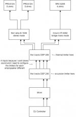
My setup:

Speakers:
2x JBL PRX412m for the high frequencies (link)
1x JBL SRX828P (passive) (link)

Amplifiers:
1x the t.amp E-1200 for my tops (link)
1x Crown XTi 6002 for my subwoofer (link)

Frequency Splitters:
1x the t.racks DSP 206 (link)
1x the t.racks DSP 408 (link)

I have a mixer, which receives signal from a DJ controller.
The mixer then will send the signal to the DSP 206 which will send the signal to the DSP 408.
The DSP 408 will then send the signal to the amps which are connected to my speakers.

Limiting:
My goal is to set my limiters (excursion and thermal) on my frequency splitters (excursion on the DSP 206 and thermal on the DSP 408). The limiters should be set to a level, where to gain of the amplifier can be set to the maximum. This way I do not have to watch my amps all the time and I can still be sure that my speakers are protected.
I've used the limiting guide by linea research (link). Since I want to set my limiters before my amps I have to take the amplifier gain into account (see page 2, bottom chapter of the file).

The problem is now, that I don't know my exact amplifier gain in bridge mono mode. In the owners manual of the XTi there is only a gain for 8 ohm output. However I run my amp for my sub in 4 ohms. So I just measured the voltage gain. In this guide is also stated that some amplifiers have not a fixed voltage gain. So measuring is the best option.

After my measuring I've got the following values (these are all measured with the gain turned all the way up):
the t.amp E-1500 (set to stereo mode): 0.5V into channel 1 generated an output of 57V at channel 1
Crown XTi 6002 (set to bridge mono mode): 0.5V into channel 1 & 2 generated an output of 73V at channel 1

This brings me back again to my questions above. How do I calculate the gain of my amplifier?
Since I have put the XTi to bridge mode I would assume, I have to calculate the gain with an input of 1V. Which means a gain of 73x (equals to 39.48 dBu)
However my gain of the t.amp would be calculated with an input of 0.5V because it was running in stereo mode.
This would mean the voltage gain of the t.amp is 114x (equals to 43.36 dBu).

I hope my questions are understandable and I would be glad for any help.

I've also put some "abstract pictures" of my setup in the attachments, which may help to better understand the setup and how I measured.

Cheers.

Attachments

  • setup.jpg
    setup.jpg
    32.6 KB · Views: 117
  • measurement.jpg
    measurement.jpg
    18.9 KB · Views: 118

Dumb MTH30 amp question!

Hi,

Firstly great forum - it has helped me a lot!

I have a probably dumb question. Have an mth30 tapped horn sub running off a bridged crown xls1502- 1050w 8 ohm available.


The driver is p.d 12sb30. 400w rms 7mm xmax 8 ohm. Ive never hammered it but have set a brickwall limiter on ui24 at point when i heard a tiny bit of distress. Its hi passed at 45hz and low passed at 120hz via dsp on amp.

Using an online calculator gives around 56v. So I guess feed pink noise and set to 56v max?

But the figure given by precision devices is rms - not sure what is safe to set for this driver in this cab... Music is live reggae generally.

Any advice gratefully received!

In future hope to build another mth30 and hope to run 2 bridged from the same crown amp ( at 4 ohm is rated1550w). Does this sound doable or even sensible?!

Cheers!

Al

Improving Polk R15/T15 cross over

Hi,
I recently built a chip amp with LM3886 and looking to build a pair of speakers to go with it. I currently have a pair of old Polk R15 (which is the same as T15) which is OK for background music. I have these for 15 years but not get much use.

The speakers are often bashed by reviewers, especially, on axis performance being worse than off-axis due to phasing issue. I did search on this forum and google but there is not much information on modification of the crossover. The stock "crossover" is single capacitor at tweeter itself.

I'm not sure if building a new pair would be better off than modding. Drivers availability here in Thailand is quite ok since we got major brands, like Dayton, SB, Scanspeak, Peerless, Fountek, Seas, Fostex, HiVi, etc.

If build a new pair, I wanna limit budget to $150-$200 for set of drivers and crossovers, excluding enclosure. Maybe something with around 5-6 inch woofer.
If modding the R15, I wanna limit the mod to crossover since I think it's doesn't make sense to spend much to replace drivers. The speakers are $170 brand new in Thailand.

Please share your thoughts and recommendation.
AP

Challenger amp placement

I'm upgrade the stereo in my Challenger, came with the Kicker 13 speaker system
HU Pioneer DMH 2660 nex Already installed with meastro and needed harnesses
Fronts Kenwood KFC-XP6903C 6x9 and 3 1/2 components so everything fits in stock locations
Rears KFC-X174 6 1/2
Amp JL RD900/5 70x4 and 500x1 to power it all
I want to put the amp under the trunk liner where the spare tire would be if I had one. Will it overheat being under the trunk carpet? Pic of where I want to put it

Attachments

  • amp.jpeg
    amp.jpeg
    560.8 KB · Views: 90

Sources for tubes

This is killing me, what is the best place for tubes that are dealers for KR or emission lab? The web page gives a list on non dealers, but little in the way of authorized dealers. Worse, the only ones I can find are on the non dealer pages.
I sent notes to all of the vendors for dealer information, I suspect they will be helpful.

thank you very much.

Is It Live Coincidental Experiences (or is it Memorex?)

Well, it happened again. Wife and I were taking the doggo for a short walk, down this small trail between houses used by the grammar school kids to cut through neighborhoods. I heard someone playing a violin and immediately, unmistakenly could tell "That's real; not someone's stereo / boombox / Alexa / Sonos / etc"

The recognition is so uncanny I couldnt even trust myself - I had to quit following her and go investigate. Sure enough, at one home's back porch, someone was playing a real instrument, live. "Where'd you go?" "I just had to see if what I heard was real or not".

Anyone else have this happen on occasion? Like riding a bicycle through a park, someone somewhere plucks a string on a guitar and BAM! the sonic recognition is immediate. I'm 65 and still the live and real is heard that way; reproduced is like a stale bag of chips in comparison.

Wish I knew what the key was - and could get my "HiFi" system to trick me in the same way consistently.

Altec VOTT for home listening with a Marantz Receiver?

I have been building on and off PA cabs for Djing, I have built BFM and now currently building a 3 way reflex with a 10"x1" horn top separate. I have bought many speakers and amps over the years Crown, QSC, Hafler,Technics, Behringer DCX, Sansui, ADC and recently an Ashly analog crossover for my 3 way.
I have a passion for good sounding equipment. I still have the DJ/PA sound equipment, but I do miss my old pair of Altec 14 monitors which my brother has now since bought new from Crazy Eddies in NYC. I have used these in my early years in mobile DJ with a 75 watt per channel Technics integrated amp with an ADC top of the line EQ. I liked the sound of these with vinyl in the early 80's when the Disco Boom was in full force.
Now I have been looking on eBay on and off for an original built plywood Altec VOTT A-7 cabinets empty. I heard a pair all original with the 500 horn playing Earth, Wind, and Fire in AES show 10 years ago Jacob Javitz Convention Center and loved the sweet sounds I am hearing with a harder impact overall to the sound in an analog group section of the show.
I was amazed with the sound, I am planning to buy a pair of A-7 VOTT cab empty and will load with original Altec 421 15" woofers from Great Plains and the 1" and have someone build original pair of Altec passive crossover with optimum components custom?
But I would like to use either a Marantz 2270 receiver or 2285B with 70 watts and 85 watts available. Would I need to go Marantz 2325 (125 w/channel 8 ohms) to power these pair for home listening but able to go higher volumes when there is a dinner party to impress my guest?
Thanks for all the help and suggestions.🙂
Projects by fanatics, for fanatics
Get answers and advice for everyone wanting to learn the art of audio.
Join the Community
507,349
Members
7,866,489
Messages

Filter

Forum Statistics

Threads
405,205
Messages
7,866,489
Members
507,349
Latest member
testuser60