Hi everyone,
I am a serious (but amateur) classical pianist that no longer has the ability to use an acoustic grand piano due to noise constraints, so I purchased the Kawai Novus NV10 digital piano. This is a hybrid instrument that uses a real acoustic grand action mated to optical sensors and a digital piano cabinet. So, you get all of the feel of a real acoustic without the noise.
There is just one problem - the built in audio is atrocious given the cost of the instrument. The only way I can get good sound out of it is to hook it up to my computer and use it as a midi controller with Pianoteq software and my Sennheiser HD650 headphones. But the speakers are horrendous, so I figured I would open it up and take a look.
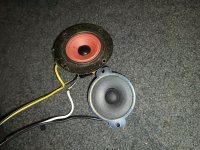
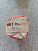
Frankly, this sound system seems like a complete afterthought to me from both an architectural and quality standpoint. The woofers feel cheap, there is no real crossover network, there is point-to-point "fix it" wiring on the mainboard, and the system is generally underpowered.
Given the poor design and components of the system, I am wondering if I can simply take the audio output off of the mainboard, run it through something like a miniDSP and then directly to my own amplifiers and replacement drivers?
I spent some time today and drew up a schematic of the way the sound system currently works.
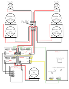
Looking at it, I have several questions:
1. It seems that the mainboard has separate audio outputs for L/R channel and bass. I assume this means a digital crossover for the bass woofer? This is one issue that I may have to figure out that could impact driver selection.
2. I do not understand the pinouts or number of wires used on this system, it does not seem logical. For example, there are five wires coming off of the mainboard for the L/R channel output, which corresponds with five pins in the input of the Amp. But when the output of Amp 2 is daisy chained with the input of Amp 1, there are only three wires. Why?
3. Why does the bass signal need to be pre-amped, but the L/R channels do not?
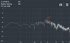
4. Is there a way I can find out whether or not the signal coming off the mainboard is flat or processed to hell?
Here are some more pictures of the system. I would really appreciate any help!
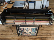
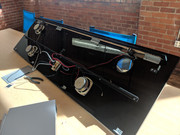
View of the action with the cover off
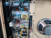
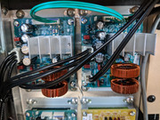
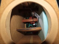
Amplifier Section
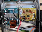
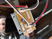
Bass amp and Preamp
"Crossover"
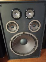
How the drivers are mounted to the lid of the piano
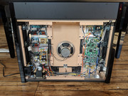
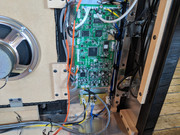
View with back cover removed
Close up of L/R channel amps
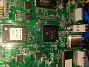
Mainboard
Mainboard 2
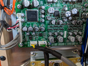
Mainboard output section


