Hi Guys
i was wondering which is better performance and audio quality in the output stage the NJW pair or the Toshiba 2S Pair .... i bought many counterfeit Toshiba transistors so looking for replacement and i think this pair is good.
waiting for ur replies
i was wondering which is better performance and audio quality in the output stage the NJW pair or the Toshiba 2S Pair .... i bought many counterfeit Toshiba transistors so looking for replacement and i think this pair is good.
waiting for ur replies
I use many of them. They are good quality, and the parameters are quite uniform. The sound quality is better than the Toshibas, but of course this is just my personal feeling.
Sajti
Sajti
Pretty damn similar when you compare the hfe vs Ic in the datasheets:
http://www.onsemi.com/pub_link/Collateral/NJW0281-D.PDF
http://www.fairchildsemi.com/datasheets/2S/2SC5200.pdf
http://www.fairchildsemi.com/datasheets/2S/2SA1943.pdf
In any decent amplifier design they will sound identical.
As above a real transistor from a reputable manufacturer (OnSemi, Fairchild, ST) purchased through a reputable distributor (Digikey, Mouser, Element14/Farnell) is better than a fake Toshiba one and no worse than a real Toshiba.
Last edited:
Well... AndrewT , Sajti , TMM .. Thank you guys .... you really made me very determined on buying them with no hesitation .. Farnell Egypt offering them with alot more lower price than Toshibas ... thats why i made this thread
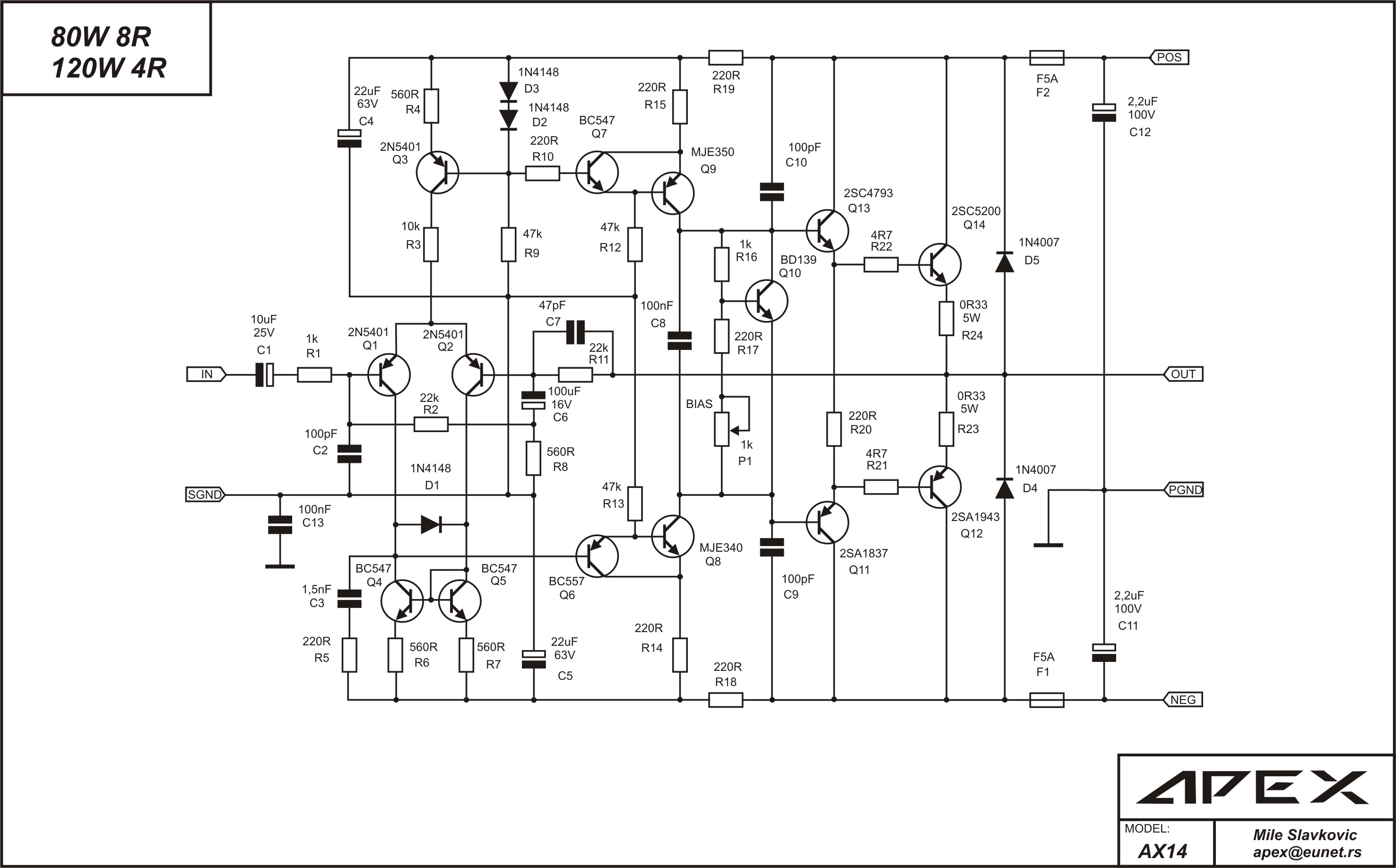
i just finished the APEX AX-14 Amp with the 2SC5200/2SA1943 ... the power output i think is good the heating of the output pairs is normal due to biasing current ... just the sound quality is not high definition ..not bad but not hifi.... could this be due to toshiba fakes or just feeling??
ooooh F.....k China and counterfeit .. i'm going crazy
ooooh F.....k China and counterfeit .. i'm going crazy
It can be anything. The Power amplifier is very complex system, with many important parts. Fake output is only one of them... It's very easy to produce bad sound quality...
Sajti... i know that ... but the AX-14 is tested and built by many members here... so i just wonder does the sound quality and rated output power affected by the transistor quality... i mean it's working it should be around 80w/8ohm but i think it's not more than 40w/8ohm ... do a counterfeit transistor do that ??
Ha!!! Looks like your transistor can work slightly better than the bigger brother of your transistors....MJw3281 and 1302 I bought. I use 5 pair of transistors per channel, power is not the most important thing for me.
I just tested. MJW3281 and 1302. The matching is superior out of the tube. Maybe yours are just as good, be interesting if you buy more and test them too. Here is my test result:
http://www.diyaudio.com/forums/solid-state/275364-mjl3281-vbe-matching.html
When comes to transistors, I definitely buy from digikey, Newark etal. I buy Chinese resistor on ebay because I actually measure them before putting them in. It's not worth it to go cheap on transistors. You want cheap, buy a used amp on ebay. When you build, you want to do better than brand amps.
Last edited:
Sajti... i know that ... but the AX-14 is tested and built by many members here... so i just wonder does the sound quality and rated output power affected by the transistor quality... i mean it's working it should be around 80w/8ohm but i think it's not more than 40w/8ohm ... do a counterfeit transistor do that ??
The output power usually not affected if the output devices are fake. Fake output devices go smoke, if You push them heavily, because of the small chip inside. Anyway, if You believe, that Your amplifier should sound better, let's try to make it better, with change of components. It's a good game to play, and You can learn a lot with it!
Sajti
Thanks a lot sajti...this way .. i think they are not fake .... i increase the bias current to the maximum and the output pair get very hot but doesn't go away.... but the most weired thing is by increasing bias current the output pair gets hot but the output power doesn't effect ... even if i turn the bias pot to the minimum bias current the output still no effect at all !!!!
the amplifier should run with +-50vdc i run it with 40vdc ...but i dont think that this 10vdc make this problem isn't it??
the amplifier should run with +-50vdc i run it with 40vdc ...but i dont think that this 10vdc make this problem isn't it??
the amplifier should run with +-50vdc i run it with 40vdc ...but i dont think that this 10vdc make this problem isn't it??
The output power is mainly depended by the power supply voltage, not the bias current. 40V instead 50 means 36% loss of power!
Sajti
okay that's the reason of the low power ... but what about the bias current adjustment... i installed two 10ohm resistors in series with each supply rail ... but no current was flowing into the emitter resistors .... some one in the SlewMaster thread faced something like that and he said that's becasue of the pre driver trannies ??
So, did you measure the voltage across these 10 ohm resistors to determine the current drawn by the amplifier? Being only 0,33 ohms, the voltage drop across the output transistor emitter resistors for say, 50 mA bias current, would only be 16 mV - a very small voltage. Is your voltmeter sensitive enough to measure this? Be assured though, if your heatsink is slightly warm, bias current will certainly be flowing. Carefully check the circuit around Q9, which is the bias controller and varying P1 should give you plenty of current adjustment but don't set above the recommended current unless you want to risk thermal runaway.... i installed two 10ohm resistors in series with each supply rail ... but no current was flowing into the emitter resistors ....
An externally hosted image should be here but it was not working when we last tested it.
Ian .. the heatsink get worm and hot and the amplifier is working ... the only problem is that i couldn't measure the voltage drop across the 0.33 resistors ...when checked every emitter resistance alone with reference to ground it measured a constant 12mvdc !!!
If you cannot measure across the resistor, then you have to measure the output to ground with no signal to get the offset voltage. Then do subtraction to get the true voltage across the emitter resistor.Ian .. the heatsink get worm and hot and the amplifier is working ... the only problem is that i couldn't measure the voltage drop across the 0.33 resistors ...when checked every emitter resistance alone with reference to ground it measured a constant 12mvdc !!!
For the sake of talking only, if you only have 12mV across the resistor, your bias is too low for the 0.33ohm resistor. You need to adjust to have 26mV across the resistor to minimize the crossover distortion. This is to follow the Oliver's condition to minimize the output impedance change during crossover point. If the amp already getting very hot, and you don't want to increase the bias, then change the resistor to 0.68ohm and adjust to have 26mV across the resistor to minimize the crossover distortion. A 0.5ohm resistor would be the easiest to get, then you increase the current only a little to get to 26mV.
Last edited:
well..Alan ....... the measured 12mv value is not affected by the bias trimer... i mean i turn the trimer counter clockwise the output pair is just worm and when turn in clockwise the output pair is very hot... note that : all this done without any effect in either sound quality or sound power.... do i need to increase the the rail supply resistors from 10R to say 100R.... or imay just need to change the BD139 (predriver) with another one???
by the way sorry for long description i mean simply " There is no bias control or measure" So simple 😀
I just looked at the Apex AX14, it has bias adjust!!
I don't think changing the transistor will fix your problem. You better find out what is the bottle neck of the sound quality. there are so many factor that affect the sound quality and power amp is only one of the many factors.
I remember when I had the Acurus amp ( so so in audiophile) and a pair of Kef floor standing UniQ ( less than so so!!). It worked really well for the money. Then I went and got a pair of JM LAB 913 series, I hooked it up, it was very disappointing. I was so worry. Then I experiment with the speaker cable. I start pairing up the 12 gauge monster like cable. Every pair I added improve the sound. The sound just "popped". The improvement only stopped after the 4th pair of cable per side. I use 2 pair in parallel for the mid and tweeter, two pairs for the woofer. Then adding the 5th pair does not seems to make any difference.
I can tell you, when I just switch the Kef the JM Lab without changing the cable, there is hardly any improvement. Now, it is day and night difference. The sound becomes 3D with transparency and depth, it just comes alive. The improvement is astonishing.
I still using the cheap Harmon Kardon receiver as preamp. I tried an expensive preamp and it did not sound as good. So I stay with the HK all these years.
My point is trouble shoot your problem first. Your room, move the speaker around. try a different music source, a different DVD/CD player, try a pair of better RCA cable. they do make a difference. I moved to a bigger house, somehow, the sound is not as good as the old house. Maybe it's the hardwood floor. The better the system, the more critical everything is, even the surrounding. There is a good reason why they have hifi furniture, a foam roll, panel etal. the higher the quality, things that never a problem becomes one.
Then you might have something wrong with the power amp also. Don't blame on the power transistor, that's the last thing I would look at. If you said you cannot hear the difference when changing the bias, I believe something else is the bottle neck that you cannot even hear the improvement. The system sounds only as good as the weakest link in the system. My Acurus was biased quite cold, like 13mV across the emitter resistor. When I increase the bias, there is a distinct improvement. I am running 100mA per pair now. I did not change the resistor because I am lazy, and also at my listening level, I never get out of Class A, so even if I did not do the Oliver's optimization, I can get away with it for now.
JMHO.
Edit:
I look at the schematic. One thing stood out to me is it's a 120W amp, but with only 1 pair of output transistors. I am no expert, but I am not comfortable with this. I don't know what you can do. I would have used at least 3 pairs. May be I am way over kill, but at least I would like to see 2 pairs. Hell, I am OCD, I am using 5 pairs in my power amp and I am doing less than 100W but with 200mA per pair to give like 10W of class A power. In your case, you might want to consider MJW1302/3281 that has a bigger package and designed to handle more power.
Last edited:
We are getting over-complicated here with irrelevant issues and operating conditions. This is a popular, proven DIY design here by member Apexaudio. The issue is with this particular build where the bias adjuster doesn't seem to work according to the voltmeter measurement but somehow the bias current must be varying because the heatsink temperature varies (assuming this is not a warm-up time delay matter).
So, either your meter is measuring incorrectly, the wrong channel in a stereo arrangement is being adjusted or there is a strange circuit error. You could be measuring at the appropriate test points but adjusting something that is unrelated. Check the soldering and terminals of P1 so that the correct terminals and connections according to the schematic are used.
Try this variation: Measure across both emitter resistors. That is, between the emitters of Q12 &13 instead of from one emitter to common. Ensure nothing is connected to the output terminal and loading it.
Now:
Do you measure twice the voltage drop at 24 mV now?
Does the measurement vary now with P1 adjustment?
Does the temperature of the heatsink still vary in warming and cooling?
Do you have Q10 attached properly to the heatsink or one output transistor case?
- Status
- Not open for further replies.
- Home
- Amplifiers
- Solid State
- NJW0281G / NJW0302G instead of 2SC5200/2SA1943