Hi Comnoz,
cor blimey...your amp really meet my taste of design. I love these lab look, like in old science movies.😀 And this neat meters...
I also got an ongoing project with an high power transmitting tube amp.
But the work ist slow down due to my back problems .
The main work , especially the mecanical is done. The opt is wound and most of the major parts fitted .
I separated the high voltage power unit from the amp. The aux mains trafo is located on the amp chassis.
The output tubes are 2x GU-81, the driver 2xEL34 , the input amp are 1xE88CC and 2x EL803. Estimated output 1,2kW +Vplate 2,3kV. Mains input power at full blast 3.5kVA/ idle 0,8kVA.
The HV mains unit is still a makeshift version with 3 identical xfmr , each got 230V prim / 820V sec. . the 2300V are derived with a greinacher doubler .. The primaries they run on 3 phases, four wires in star circuit 230/400V.
Three phases operation got the advantage of less ripple on the dc side .
I hope I able to finish this amp stil this year.. here some pics from the construction.
The drawings of the amp will not get into the attachment window . I will find out later why. It took only the drawing of the HV mains supply .
73
Wolfgang
Attachments


Becks beer -my kind of guy.
Love to see the big amps going together. I was worried about ripple in the B+ to begin with but with a little choke and plenty of capacitor the push pull outputs don't seem to mind the ripple that's left.
Do you plan on using fet followers for the driver tubes. The big transmitter tubes really respond to positive drive on the grids. Comnoz
my new overkill tube amp. Just what I wanted for my little shop.....Output tubes are 4-250's in the video with 2000 volts on the plate and 600 volts on the screen. With these tubes it makes 150 watts per channel
Congratulations on building a big amp, and actually making it work! There has been considerable talk of building the "big one" but few amps are actually built, and even fewer actually work. I built an RF amplifier that used a 4-400 on about 3500 volts to produce about 1KW back in 1977. That thing scared the bleep out of me and I gave it away!
Love to see the big amps going together
I have been guilty of talking a lot about building a big one, but the reality of actually building it hasn't gotten very far. A crude and rather unsafe "breadboard" test about 10 years ago started me down the transmitting tube route, but I wasn't happy with the results and never took it any further. I was squeezing about 200 watts from an 833A on 1500 volts Picture#1
Several years later another breadboard test managed to squeeze out 500 watts from 4 overworked TV sweep tubes on 650 volts. This convinced me that my "big one" would use TV tubes, but no amp ever got built. Pictures #2 through #4.
Lately though I have quietly collected all of the necessary parts to build my "big one" and preliminary circuit design and testing is underway. Like all successful projects, I have set some goals and have some circuit designs in mind.
My main two main goals are conflicting and considered crazy by some. They may ultimately impose restrictions on the ultimate amp design, and some compromises may be needed.
#1)I want to build an amp that I can carry up the basement stairs by myself if necessary, and would prefer it to all be on one chassis.
#2) I want it to be powered by a US spec 120 volt 15 amp AC outlet. That limits the maximum line power input to 1800 watts, which will restrict the maximum power output to about 400 WPC unless some of the efficiency improvements that I am exploring actually work.
I have 240 volts at up to 50 amps available if necessary, and could use a two chassis design if needed, but for now I am exploring the possibility of a single chassis 500 WPC tube amp that I can carry myself.
I will start a new thread as testing progresses. You stated that your amp took 2 years of nights and weekends, and this one may do the same, so I don't expect to start the actual build until I have something on the workbench that meets most of my requirements and survives some of my torture testing.
Attachments


Tubelab,
Watching your exploits over the past few years has helped keep the fire going to build this thing. Thanks.
I considered using switching supplies and trying to keep the weight down but then what would I do with all the old iron I have collected over many years. The amp chassis I can lift. The power supply on the other hand is over 300 lbs! I will be getting out the cherry picker when it comes time to move it to the rack with the rest of my stuff.
I built the power supply with enough capacity to handle 3 amps. The High frequency amp is finished and in use, using 4 -6bg6 tubes and a 12ax7 [with power drive].
It will supply all but the B+ for the next amp which will be a pair of GU46 tubes optimized for the under 100hz frequency range. Parts are gathering.
Overkill -just right..... Comnoz
Well, I guess I could have used green paint.
In comparison to my CNC machine and hot tub, it doesn't pull much -and I know which one gives me more enjoyment.
In comparison to my CNC machine and hot tub, it doesn't pull much -and I know which one gives me more enjoyment.
It seems to me that by those places, energy is cheap.
Are those amp "green"? ;-D

Sure, somewhere at the end of alphabet 😀😀😀😀😀

I'm currently in the antipodes.
Cool, then everything balances out.....🙄
I started sun energy a as hobbie. Now (almost in my town), is a necessity.
Please, continue the topic.
Please, continue the topic.

Are those amp "green"? ;-D
When there are class D amps out there with total efficiencies in the high 80% to low 90% range, can you consider any tube amp "green?"
I'm looking at either 8 or 12 big TV sweep tubes in the output stages, each with a 16 watt heater, plus the driver circuitry's heaters. I am still testing and ironing out the kinks (OK huge cracks) in a cathode follower output stage with a class G rail switching design. If successful the driver gets another pair of smaller sweep tubes, so there is 200+ watts burned off as heat before the B+ is even switched on.
I built a class A SE amp 10 years ago using 845 transmitting tubes for 40 WPC. The amp puts out about 400 watts of heat, which made it almost unusable in south Florida where the ambient temperature is in the 80 to 90 degree F range for most of the year. I needed another 600 watts of air conditioning just to keep my tiny room at a livable temperature, so I was blowing a kilowatt just to play music. That amp sounded real nice, but didn't get used much.
Here in rural West Virginia, a few hundred watts of heat just means that I can turn off another heating appliance for a good portion of the year. The uninsulated basement can get cold, and stay cold for several months in winter.
Does anybody need a kilowatt tube amp? Does anybody need a 500 horsepower car? I did the 500 HP car thing several years back. South Florida traffic is so thick that it just idles along, and the closest race track was 50 miles away, so.....it's time for the kilowatt tube amp....do I need it? No, but this one will be tuned for a real smooth idle!
Wow, really cool amp and I loved your choice of music for the video. One thing is for sure, if visitors go finger-pokin they will only do it once!
BillWojo
BillWojo
Does anybody need a kilowatt tube amp?
me? no....but the idea of being able to make one is truly titillating.....😀
Hi ,
here are the schematic of the amp .
The complete amp consist of
the amp circuit itself
the aux mains supply for the heaters, input, voltage and driver amp.
the protection circut
and the operating unit.
The HV supply shall be a separate unit due to the weight
I will come up later with the other drawings when I find time to make them readable for others than me. Actually they are scratch on a piece of paper.😀
When the amp finally work. (I hope so!) I will design a HV switchmode supply to avoid the heavy transformer. I still got the ferrite cores, the strandes RF wire ,kapton paper, super fast hv diodes, switching IGBTs and the control device.
A friend has carring all heavy parts into my shack today. So the final test move slowly closer. 😀
Edit:
here how I compensate my power consumtion. 24 Modules with 4 kW peak produce aprox. 3500kWh /year.
The meters show the output on a wet november day 2016 short after fitting the panels on the roof. On the pic you can see the scaffold which was left for another few days before the roofers removed it.
73
Wolfgang
Attachments

Last edited:


Still working on a schematic.
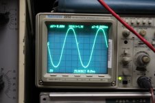
The 4-400 tubes sure do sound good but they definitely make my 2000 volt 1.5 amp supply work hard. The scope is at 20 volts per division.
https://youtu.be/C23_f7y8KVA
The 4-400 tubes sure do sound good but they definitely make my 2000 volt 1.5 amp supply work hard. The scope is at 20 volts per division.
https://youtu.be/C23_f7y8KVA
- Status
- Not open for further replies.
- Home
- Amplifiers
- Tubes / Valves
- High Power Tube Amplifier