Hi,
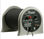
My Messina GSSAMP-01 stopped working.

After investigation I discovered that the 250V 1 AMP fuse was blown.
I replaced it and it immediately blew again.
I tried with few fuses, and it blows up immediately.
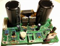
Took it apart.
The board inside is marked:
Indigo 600063 Rev. 13

There are two MOSFETS
IRF 9530 (tests ok)
IRF 530 (tests short)
The IRF 530 has a glued part to it, looking like a Zener diode, but it's not as there is no cathode line on it.
Considering that it is glued on it, I'm suspecting some kind of a thermal cut-off, but have no way of confirming it or knowing what part / specs
Any clue as what it is, and what it can be replaced with?
Also the IRF 530 comes in both P and N forms, this one has neither N or P marked on it, how do I know which is it?
Lastly, the local shop did not have anything equivalent to IRF530
Which is 100V 14A
What can it be replaced with?
The closest the clerk was able to provide was IRF740, which is 400V 10A
Is it safe to use higher voltage (I suspect yes but am not certain)
What about the current, 10A instead of 14A?
is it the total VA that matters 4000VA for IRF 740 and 1400VA for IRF530
or do I need to get precise rating?
My apologies for rather noob questions, trying to get the Amp going again.
Any advice is greatly appreciated.
Thanks in advance
Bing
My Messina GSSAMP-01 stopped working.

After investigation I discovered that the 250V 1 AMP fuse was blown.
I replaced it and it immediately blew again.
I tried with few fuses, and it blows up immediately.
Took it apart.
The board inside is marked:
Indigo 600063 Rev. 13

There are two MOSFETS
IRF 9530 (tests ok)
IRF 530 (tests short)
The IRF 530 has a glued part to it, looking like a Zener diode, but it's not as there is no cathode line on it.
Considering that it is glued on it, I'm suspecting some kind of a thermal cut-off, but have no way of confirming it or knowing what part / specs
Any clue as what it is, and what it can be replaced with?
Also the IRF 530 comes in both P and N forms, this one has neither N or P marked on it, how do I know which is it?
Lastly, the local shop did not have anything equivalent to IRF530
Which is 100V 14A
What can it be replaced with?
The closest the clerk was able to provide was IRF740, which is 400V 10A
Is it safe to use higher voltage (I suspect yes but am not certain)
What about the current, 10A instead of 14A?
is it the total VA that matters 4000VA for IRF 740 and 1400VA for IRF530
or do I need to get precise rating?
My apologies for rather noob questions, trying to get the Amp going again.
Any advice is greatly appreciated.
Thanks in advance
Bing
Attachments
Hi there,
I have the same problem and still trying to fix it.
I replaced the 2 MOSFET and all the caps and it is still blowing fuse.
Have you found a fix for yours yet?
Think we can share resources.
Cheers
Andy
I have the same problem and still trying to fix it.
I replaced the 2 MOSFET and all the caps and it is still blowing fuse.
Have you found a fix for yours yet?
Think we can share resources.
Cheers
Andy
I suggest you not use the IRF740 or 640.
first you need it be "closest match" the manufacturer decide to use IRF530/9530 he now what he's doin'.
if you don't have this 2 mosfets replace it with IRF540 & IRF9540 this is for sure better solution.
the other part that looks like diode it's NTC thermistor for the Thermally compensated bias.
first you need it be "closest match" the manufacturer decide to use IRF530/9530 he now what he's doin'.
if you don't have this 2 mosfets replace it with IRF540 & IRF9540 this is for sure better solution.
the other part that looks like diode it's NTC thermistor for the Thermally compensated bias.
Hi,
the indigo PCB is the same of Boston PV600. There are IRF 9540 and 640 on it.
Anybody known how to set the bias???
Thanks.
the indigo PCB is the same of Boston PV600. There are IRF 9540 and 640 on it.
Anybody known how to set the bias???
Thanks.
Yes, mine is from the Boston PV600. I have replaced both the MOSFETs but blows fuse again immediately. Resistors are ok and have changed all the electrolytic caps. Something else is wrong.
What type of MOSFET? Trafo is OK? Polarity of caps is OK? No shorts on PCB? Is MOSFET plate insulated form chassis ground?
Yup, replacing bad parts is just half the problem.Yes, mine is from the Boston PV600. I have replaced both the MOSFETs but blows fuse again immediately. Resistors are ok and have changed all the electrolytic caps. Something else is wrong.
You *may* get lucky but usually still there´s "something else" which you must find, you can´t just "guess".
At least, try to get original schematic and post it here, we might suggest something.
Thanks for the postings guys.. Did a search and nothing on schematics. Have also asked Boston support but never got a reply 🙁 .
Thinking of ditching the board and replace with something from Ebay like :
L15D-SMD Assembled Amplifier Board Class D IRS2092S IRFI4019H Amp 250W 4Ω MOSFET 7438300207011 | eBay
Thinking of ditching the board and replace with something from Ebay like :
L15D-SMD Assembled Amplifier Board Class D IRS2092S IRFI4019H Amp 250W 4Ω MOSFET 7438300207011 | eBay
This board has leaded components which means it is repairable without a microscope and a $600 solder workstation. That makes it worth some effort.
It is a 6 transistor amp with no IC's. You should be able to draw the schematic from looking at it. Look at another 6 transistor nfet amp schematic then check differences from yours (like the "expensive" NTCR temperature sensor). I'd download a 50W ampeg guitar amp schematic or something from eserviceinfo.com Or look on instruments amps thread for 50w amps, and ignore the effects loop.
Usually when an output transistor blows, the rail voltage rampages out the gate line and blows the driver transistors too. Then the voltage leaks out of that base or gate and that usually blows up the predriver. You have to check those too once you find output transistor is blown. Plus various diodes and maybe low voltage capacitors and low wattage resistors. Plus the emitter resistors usually too.
If you use a light bulb limiter on the AC feed, or a 6 ohm 50 W resistor on the Dc feed to the board, you won't be blowing fuses at $1 a pop if it is not fixed. Instead the light bulb will light up. Stable amps with no signal, the input current is too low to light up the bulb.
Last edited:
RE: Indigo 600063 REV 13 Board
Hi
If any one is looking for a replacement PCB for the indigo 600063 rev 13.
I made a new rev which is same design but a few changes. Works great on a
recent repair for a customer with a tannoy PS 110.
Email me at: info@newroc.ca for more details and pricing.
Cheers
Hi
If any one is looking for a replacement PCB for the indigo 600063 rev 13.
I made a new rev which is same design but a few changes. Works great on a
recent repair for a customer with a tannoy PS 110.
Email me at: info@newroc.ca for more details and pricing.
Cheers
Fuses usually blow for a reason. Sometimes its a mains transient and you get away with just replacing the fuse - however if not, then just repeatedly trying new fuses can cause more damage...I replaced it and it immediately blew again.
I tried with few fuses, and it blows up immediately.
- Home
- Design & Build
- Parts
- MOSFET Replacement and unidentified part
