I have a transformer with 3 secondaries, one of which puts out 9.5v, I would like to reduce that to 7ish volts before the regulator board, which will draw about 1amp.
Can anyone advise me the best way to go about that?
Can anyone advise me the best way to go about that?
It will be loaded with about 1 amp, I haven't measured it but I could.
The regulator board will work with the 9.5vac but it's recommended to lower the volts to 7ish.
If I knew that when I ordered the transformer I would have lowered the secondary voltage.
The regulator board will work with the 9.5vac but it's recommended to lower the volts to 7ish.
If I knew that when I ordered the transformer I would have lowered the secondary voltage.
Ordinarily it would be cheaper to modify a linear regulator board with more heat sinks or a better pass transistor or whatever. If switching regulator, mods require too much expertise to do.
However, dropping only 2.5 v you could use 3 diodes series for example. Don't use 1 amp diodes like 1n4004 etc, it runs them too hard at full amp rating. use 3 amp diodes. voltage drop these days is often .4 or .45 v instead of .7 of seventies silicon diodes, so buy 5 or 6 to see what you get. Schottky diodes are .2 to .3 v so if you want to dial it in buy a couple of 3 amp versions of those in the same box. One resistor of the proper wattage would work but the load current has to be constant for that to work. diodes don't vary so much over 20-100% load change.
Don't forget some bare or perf board to install all this. You can buy standoffs & machine screws to mount it to something, but I use 1" long 6-32 screws and 1/4 air tube cut to length to make standoffs. In the metric zone use 4 mm screws 20 mm or 25 mm long. Elastic stop nuts keep the assembly from falling off in a couple of years.
Last edited:
When you load a transformer, depending on how close to the nominal current you are, it may drop 5-15% in voltage at the output. Then, your deviation from the voltage you want is less.
Indianajo's suggestion is good and valid but the first drop diodes have to form a rectifier bridge (4 diodes) or all the diodes have to be connected 2 and 2 in anti-parallel. Else you loose the double rectifying effect.
Indianajo's suggestion is good and valid but the first drop diodes have to form a rectifier bridge (4 diodes) or all the diodes have to be connected 2 and 2 in anti-parallel. Else you loose the double rectifying effect.
Thank you for the responses.
I just realised I can increase the output voltage to 7v (want about 5.25v) via jumber so perhaps I'm better off using the diodes after the output?
I just realised I can increase the output voltage to 7v (want about 5.25v) via jumber so perhaps I'm better off using the diodes after the output?
If you mean that you put the diodes after the regulator board and you need a well regulated 5.25V voltage, diodes at the output will degrade the performance seriously.

Attachments

I have a transformer with 3 secondaries, one of which puts out 9.5v, I would like to reduce that to 7ish volts before the regulator board, which will draw about 1amp.
I hope you are aware that the transformer secondary puts out 9.5V **AC** while te regulstor board works with 7 Volts **DC** 😱
Hope you are aware they are not the same thing, by any means. 😱
Then maybe that´s not a regulator board at all but a complete power supply, with rectification and reservoir caps, which also happens to regulate output (DC) voltage.The regulator board will work with the 9.5vac
IF so,please make it clear.
that screams DC to me, not AC.modify a linear regulator board
If you don't mind having the other two windings lowered by 25%, you can use this scheme:
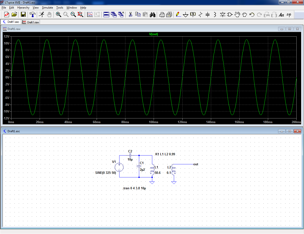
It is a capacitive divider.
If the impedance of the caps is low enough compared to the current drawn, the voltage will not sag too much under load.
Capacitor C1 must be a X-rated type; 2.2µF is the highest reasonable value for such a type. C2 can be an ordinary 100V film cap.
The circuit will draw a relatively high reactive current, but it is not important because it will not heat anything, or register on your electricity meter
Attachments

I hope you are aware that the transformer secondary puts out 9.5V **AC** while te regulstor board works with 7 Volts **DC** 😱
Hope you are aware they are not the same thing, by any means. 😱
Then maybe that´s not a regulator board at all but a complete power supply, with rectification and reservoir caps, which also happens to regulate output (DC) voltage.
IF so,please make it clear.
that screams DC to me, not AC.
Yes thats right, I tend to think of the Power Supply being the combinaion of the Transformer and the Regulator board, but as you say, the regulator board has the Bridge reciifier, caps, heatsinks etc on it. I am very aware of the difference between the AC/DC thing, there an Australian band after all 🙂

Yes, it looks doable:
Many thanks, Elvee. Now it is for DQ828 to choose.
No, one of the below options.
This is all needlessly complicating things for the OP's expertise. Note: this is not about showing how smart you guys are (I know you are), this is to help a guy with a specific issue and specific level of expertise.
He probably has already figured out he needs a rectification circuit to get from the AC to the DC.
After that, it is just a matter of adding series diodes in the +DC from rectifier to regulator until he meets his goal.
Jan
In this century, the DC regulator may be some switcher OP bought from alibaba: Which may not be specified to handle 9.5 vac in. He didn't tell us what he had. The 6 diode post faux french showed will handle either linear or switcher regulator.After that, it is just a matter of adding series diodes in the +DC from rectifier to regulator until he meets his goal.
Jan
Even if the regulator he bought is linear, he would have to cut the land on the pcb between rectifier & filter cap to insert the three diodes: plus correctly identify which land to cut. I learned how to splice into existing linear pcbs in my late fifties, it is not an obvious technique. The 6 diode solution is simpler, all off board.
BTW the technique to make a off pcb patch that doesn't pop the solder joint loose all the time, is drill a #46 hole through the board near the cut. Run #28 wire through the hole from the top, bend over cut trace, solder on land side. Coated lands may need scraping to make solder stick. Glue down the patch wire on top with weatherstrip adhesive, so it doesn't move & stress the solder joint. Don't drill holes on multilayer boards, you don't know what you may be damaging just by looking at it.
Last edited:
- Home
- Amplifiers
- Power Supplies
- Best Way To Reduce Voltage