Watch Bob Cordell's presentation at Burning Amp 2016.
YouTube
Starting at 36:31 , he covers the JC2 circuit and at 41:30 he presents a very handy trick: forcing the NJFET transconductance to match the PJFET transconductance using degeneration resistors. And then he explains why.
At 43:10 he credits John Curl for the floating tail topology.
_
YouTube
Starting at 36:31 , he covers the JC2 circuit and at 41:30 he presents a very handy trick: forcing the NJFET transconductance to match the PJFET transconductance using degeneration resistors. And then he explains why.
At 43:10 he credits John Curl for the floating tail topology.
_
Attachments


The pattern and IP protection of those unobtanium JFETs that John Curl used in 1974 are likely expired. They are NOT difficult for small foundry in Asia to duplicate.
In case you have not noticed Linear Systems has been trying for years as a serious business, it is NOT easy. No offense intended but you do not understand how this industry works.
... How easy is it to find a matched quad?
Depends on what you're matching. Idss only to a few % is doable, Idss AND Yfs (Gm) is another story... Attached is some 50-ish I have, probably fakes. Each dot is 1 unit; you can clearly see the difference between sexes.
That's why I have my plan B, using only 1 N and 1 P per channel.
Attachments

In case you have not noticed Linear Systems has been trying for years as a serious business, it is NOT easy...
Hey Scott, thanks for joining the fun.
I wonder if you've had the opportunity to look into the (2S)J103 (2S)K246? They're cheap and plentiful, and Patrick (EUVL) said they're 3x noisier than the J74/K170: if we assume 10-12 nV/SQRT(Hz), we're still looking at something like a uV or 2 over a 20 KHz bandwidth, or -120dB for line-level applications, good enough, right?
Temporarily I'm not doing much, from the data sheet the noise would be a little lower than that but for line level fine. I'm using the N-Channel part in Bob's presentation as a MM phono input. Neither Bob nor I have seen the -60dB THD that PMA showed from a single long tail pair, more like -90dB.
Scott, no, I do not. I was in the aerospace industry where copying is more difficult. I am an outsider. I admire your work on the AD797 and appreciate your participation on this forum. I wholeheartedly support IP protection.In case you have not noticed Linear Systems has been trying for years as a serious business, it is NOT easy. No offense intended but you do not understand how this industry works.
I am not talking about AD797. Toshiba and Renera/Hitachi have abandoned the FET market. What is your perspective on what would happen for hobbyist?
Last edited:
Unfortunately, Weilliang was not aware of that when he did the E4 PCB layout. If I buy the E4 kit, it will take some minor surgery of the PCB to add the degeneration resistors. It is doable.Watch Bob Cordell's presentation at Burning Amp 2016.
YouTube
Starting at 36:31 , he covers the JC2 circuit and at 41:30 he presents a very handy trick: forcing the NJFET transconductance to match the PJFET transconductance using degeneration resistors. And then he explains why.
At 43:10 he credits John Curl for the floating tail topology.
_
The Sherwood S-6040CP power amp has complementary differential input using the 2sk270a/2sj90a pair. The input has 100 ohm degeneration resistors on all four jfet. Will that make the matching easier?
Last edited:
What is your perspective on what would happen for hobbyist?
Linear Systems is one choice, I have never seen a manufacturer actually reach out to the DIY community as they do like supporting Burning Amp.
> BUT the matching between N and P is BAD!!!
If you are using them at 2mA as indicated in your spice files, then the N-P Idss match is of NO importance.
This applies equally for individually CCS biased IPS, and for floating tail.
Since you can spice, I'll leave you to find out how this works.
On top of that, if you use the source degeneration resistor, the Id will be reduced even at Vg = 0V.
Measuring Idss does not tell you the whole story.
FETs perfectly matched at Idss of 8mA or 11mA Idss do not always match (for Vgs) at 2mA.
If you want perfect match, you should always measure under operating voltages and currents.
Linear Systems Matched LSJ74/LSK170 JFET pairs (Grade B)
... and temperature controlled.
F5 power amplifier
F5 power amplifier
> At 43:10 he credits John Curl for the floating tail topology.
What he did not say is that the floating tail actually gives low distortion than 2 separate CCS tails.
It took me >10 years to understand why.
> you can clearly see the difference between sexes.
They have actually told you already in the datasheets.
If you want perfect N-P match, use 2SK163/2SJ44.
F5 power amplifier
F5 power amplifier
F5 power amplifier
F5 Headamp ?
All 10-year-old stuff.
> I have never seen a manufacturer actually reach out to the DIY community as they do like supporting Burning Amp.
I wonder which audio manufacturer are using those LN JFETs from LS, and what discount do they get.
We asked for the price for 1k once, and were very surprised how little discount.
Maybe they still have very low yield ??
Replacement For Toshiba 2SK170/2SJ74
Linear Systems Matched LSJ74/LSK170 JFET pairs (Grade B)
Linear Systems Matched LSJ74/LSK170 JFET pairs (Grade B)
Linear Systems Matched LSJ74/LSK170 JFET pairs (Grade B)
Cheers,
Patrick

I wonder which audio manufacturer are using those LN JFETs from LS, and what discount do they get.
We asked for the price for 1k once, and were very surprised how little discount.
Maybe they still have very low yield ??
Cheers,
Patrick
I asked once but that was early on, I don't see too many seriously high volume products these days save microphones and there the PFET is not needed and the capacitance of he big FET's is a liability.
The first 74's I saw were simply pushed for Idss at the expense of Vp making Yfs low. It was as if someone did not understand.
I see that the matched quad 2SK170/2SJ74 is back in stock at the diyAudio store.Linear Systems is one choice, I have never seen a manufacturer actually reach out to the DIY community as they do like supporting Burning Amp.
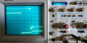
My Quasimodo is 90% up, so I tested some diodes/rectifiers with it:
I take the Schottky anytime.
- SR520: Schottky, 20V 5A
- FR608: Fast, 800V 6A 150 nS
I take the Schottky anytime.
Attachments

Last edited:
Hi everybody! I have finally found this nest of inputs regarding some of my stuff. I have learned from some of your inputs, especially in power supply optimization.
I don't know if I want to address everything I have found, but perhaps in the near future.
Zung, you probably have fake jfets, the n and p Toshiba devices should be almost exactly the same for Gm. Yours differ. (for example)
I don't know if I want to address everything I have found, but perhaps in the near future.
Zung, you probably have fake jfets, the n and p Toshiba devices should be almost exactly the same for Gm. Yours differ. (for example)
Zung, you probably have fake jfets, the n and p Toshiba devices should be almost exactly the same for Gm. Yours differ. (for example)
Not quite if you look at the datasheets.
Scott, you should more carefully check the data sheets, before challenging me. MY Toshiba handbook shows at 4ma: 28,000 for the 2SK170, and 29,000 for the 2SJ74. It is the CAPACITANCE that is so different.
Attachments


Last edited:

- Home
- Amplifiers
- Headphone Systems
- The JC2-HPA Headphone Amplifier