@kozard, I think you have high 3rd harmonics at 20Hz because you have hum from the power supply at 60Hz and this is added as your "3rd harmonic" of the signal of 20Hz. Same for "2nd harmonic" for 30Hz etc.
I was wondering about that but it is a 60 kHz switching power supply with two stages of CLC filters.
And I was wondering if it should appear as peaks of distortion at 20 Hz, 30 Hz, etc. But it seems to be a smooth function starting at 20 Hz extending to 100 Hz.
I wonder what I can do to the measurement setup to reduce 60 Hz pickup.
And I was wondering if it should appear as peaks of distortion at 20 Hz, 30 Hz, etc. But it seems to be a smooth function starting at 20 Hz extending to 100 Hz.
I wonder what I can do to the measurement setup to reduce 60 Hz pickup.
Well I have tried a number of changes and so far nothing has changed the 20/30/60 Hz related distortion.
I tried moving the star ground. Putting the chassis cover on. Shielding the potentiometer with copper foil (and grounding the foil to the star ground). Moving the speaker adapter output cable and coiling it tightly. Nothing changed.
I replaced the USB cable with a shorter and better looking one (shield looked better). No change. Turned off all the lights (some LED, some fluorescent). Nothing changed.
I tried moving and tightly coiling the shielded input (to the amp) cable. The low frequencies did not change at all. But the HF (7 kHz) distortion improved to 0.009% THD at 12 Vrms into 4 Ohms. (See attached.)
Any ideas/suggestions on fixing this low frequency issue? What can I check or try? This amplifier sounds very nice and the THD looks good, I just want to understand and fix the low frequency THD issue.
Attachments
-
 All Changes 20 Hz 12 Vrms into 4 Ohms uPC1342V.png598.8 KB · Views: 303
 -
 All Changes 100 Hz 12 Vrms into 4 Ohms uPC1342V.png582.1 KB · Views: 299
 -
 All Changes 1 kHz 12 Vrms into 4 Ohms uPC1342V.png598.4 KB · Views: 283
 -
 All Changes 7 kHz 12 Vrms into 4 Ohms uPC1342V.png594 KB · Views: 284
 -
 Second Style uPC1342V Kit First Test.jpg997.5 KB · Views: 297
Do you use a notebook computer and run it on batteries when making measurements?
I still think it is power source related, not amp circuitry related. You clearly see that in your spectrum picture at 1kHz.
Do you hear any hum from the speakers without the input signal and the ear up close to the speaker?
I still think it is power source related, not amp circuitry related. You clearly see that in your spectrum picture at 1kHz.
Do you hear any hum from the speakers without the input signal and the ear up close to the speaker?
Any ideas/suggestions on fixing this low frequency issue? What can I check or try? This amplifier sounds very nice and the THD looks good, I just want to understand and fix the low frequency THD issue.
Is it not just mains noise (50/60Hz and harmonics) picked up as a harmonic?
Make some ordinary FFTs (not frequency scans) with increased resolution in the low frequency region (use FFT length 512k or 1M).
Run first 1kHz for reference (to see the LF noise) and then LF signals (20Hz, 40Hz, 60Hz).
Do you use a notebook computer and run it on batteries when making measurements?
I still think it is power source related, not amp circuitry related. You clearly see that in your spectrum picture at 1kHz.
Do you hear any hum from the speakers without the input signal and the ear up close to the speaker?
I was using a notebook but on AC power. I did additional measurements this morning on AC and battery. While it is possible to see a small difference in 60 Hz on battery power the LF distortion does not change much at all. My audio interface is USB and 24 bits so I think I am a little bit isolated from 60 Hz from the laptop. But there is still some quite far down. (About 102 dB down from full scale output.)
With my ear up to the speaker I do not hear any hum at all. Silent. (Amplifier volume at maximum. Same with the laptop on AC or battery power.)
I have attached RTA screen shots with maximum and minimum amplifier volume and laptop on battery or AC.
Attachments


Is it not just mains noise (50/60Hz and harmonics) picked up as a harmonic?
Make some ordinary FFTs (not frequency scans) with increased resolution in the low frequency region (use FFT length 512k or 1M).
Run first 1kHz for reference (to see the LF noise) and then LF signals (20Hz, 40Hz, 60Hz).
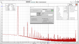
Max I can run is 128k FFT (attached at various frequencies). All are at 12 Vrms into 4 Ohms. This time I ran on battery power.
I assume that my 75 Hz measurement proves that it is 60 Hz? Where is it coming from since there is almost no 60 Hz when the amplifier is at maximum volume but no input? I am surprised since it is a SMPS with massive filtering. (Especially massive considering the switching frequency.)
1st LC filter has: 4x1000uF low ESR inside the SMPS per rail.
2nd LC filter has: 4x2200uF low ESR added outside the SMPS per rail.
3rd C filter (on each amplifier module): 6800x2 uF
I guess under load my SMPS somehow has fairly big 60 Hz noise on the output? But almost nothing unloaded? I was hoping the SMPS would not do anything like that.
Is my interpretation correct? I need to still somehow improve the power supply but that the amplifier is ok?
Attachments


From what I see, it looks pretty normal for me - quite normal spectrum with mainly 2nd and 3rd dominating harmonics. If you don't hear any LF hum from the speakers, I would not go crazy about the measurements in LF - this is not the most sofisticated measuring equipment anyway. So - enjoy your music! 🙂
From what I see, it looks pretty normal for me - quite normal spectrum with mainly 2nd and 3rd dominating harmonics. If you don't hear any LF hum from the speakers, I would not go crazy about the measurements in LF - this is not the most sofisticated measuring equipment anyway. So - enjoy your music!
Sure, I agree but I want to get to the bottom of it before I purchase more amplifier board kits and power supplies. You see this is the test amplifier and test power supply and I plan to build additional channels. If the amplifier has poor power supply ripple rejection ratio I might go with one of two other Blameless designs (as opposed to the similar uPC1342V chip). If the problem is the power supply then I either need to fix it or buy/build a different/better power supply for the other channels.
The board based (as opposed to chip based) Blameless designs might have better rejection due to the two RC filters between the power section and the input section. (Maybe, I will need to measure and see.)
I also have a heavy rescued transformer from a dead receiver which I could try. (In case it is an unexpected issue related to the SMPS power supply.)
I built this uPC1342V, the MA-9S2 and a couple LJM Blameless type designs. (Over the last 8 years.) So I want to down select to the best one before finishing the multichannel setup. I like the uPC1342V because of the better VAS stage. But I might be able to modify the LJM to the better VAS but I would need to be careful I think to avoid making it unstable.
Aside, yes I am enjoying this uPC1342V. It sounds quite nice with my not very expensive ES9028Q2M & AD823 board.
Last edited:
Max I can run is 128k FFT (attached at various frequencies).
You may want to use the latest beta from REW (Room EQ Wizard) Beta Downloads | AV NIRVANA . John has added loads of great improvements since the last stable.
Max I can run is 128k FFT (attached at various frequencies). All are at 12 Vrms into 4 Ohms. This time I ran on battery power.
I assume that my 75 Hz measurement proves that it is 60 Hz? Where is it coming from since there is almost no 60 Hz when the amplifier is at maximum volume but no input? I am surprised since it is a SMPS with massive filtering. (Especially massive considering the switching frequency.)
1st LC filter has: 4x1000uF low ESR inside the SMPS per rail.
2nd LC filter has: 4x2200uF low ESR added outside the SMPS per rail.
3rd C filter (on each amplifier module): 6800x2 uF
I guess under load my SMPS somehow has fairly big 60 Hz noise on the output? But almost nothing unloaded? I was hoping the SMPS would not do anything like that.
Is my interpretation correct? I need to still somehow improve the power supply but that the amplifier is ok?
At that power level, the 60Hz noise is about 95 dB down, so it is pretty much swamped out by the signal. It is probably sneaking in through the supply. If you are using an SMPS, you could try adding larger caps across the rails, but that might prevent the SMPS from starting up correctly - they can be fussy about heavy capacitive loads (one reason I do not like them).
I would not worry about it too much - if you are sure that this is not coming from a ground loop or the wall wart for the D/A converter (use a battery for that and float everything to be sure) then let your ears be your guide. I am guessing the main effect at high power levels would be a very slight garbling of music coming from the speakers (60 and 120 Hz modulation).
I was able to measure my Hafler DH110 preamplifier. I'm having issues with stability of the measurement. It goes along and updates moving around a little and improving with more averages and then it jumps, distortion goes way up, everything climbs and then it starts averaging again and getting back to normal. I have attached a picture of the error screen.
.jpg")

Windows 8.1 on a Dell Laptop w/ 4GB memory 64bit Op sys. I've tried a bunch of buffer sizes up to 1024, the highest it allows. I've noticed it happens with both Java and ASIO.
I see the same thing often on a Windows 10 64 Bit quad core laptop (8 GB ram & SSD) using a Creative Labs USB SB0490. I am running 5.20 RC4 but it occurred on the prior stable release also.
I have never seen it on my very old Vista desktop using an EMU 1820m (PCI card + external dock).
I wonder if it is USB related. I think it occurs less often when I run my high power/high performance plan with the minimum CPU clock rate set to maximum. But it is hard to be sure with sporadic seemingly random glitches.
I'll take a look at my performance plan. I did take a look at my USB ports and made sure I was in 3.0USB port, I had been in a 2.0USB port, made no difference.
Maybe the official support forum might be helpful:
Official REW (Room EQ Wizard) Support Forum | AV NIRVANA
I just live with it but it would nice to find out how to solve it.
It is strange that it does not occur on my ancient Vista machine running a faster 24-bit interface. Yet it happens on my Windows 10 laptop. Then again my Windows 10 laptop has trouble with the SA9023 for my ES9023Q2M.
I was able to measure my Hafler DH110 preamplifier. I'm having issues with stability of the measurement. It goes along and updates moving around a little and improving with more averages and then it jumps, distortion goes way up, everything climbs and then it starts averaging again and getting back to normal. I have attached a picture of the error screen.
View attachment 904265
View attachment 904266
Do you have the averaging set to a specific number? The averaging will converge the noise to a low level but then after the specified number of averages, it starts again from the noisy display. Setting the averaging to 'Forever' will avoid it.
Jan
No, it is a rolling average.Do you have the averaging set to a specific number? The averaging will converge the noise to a low level but then after the specified number of averages, it starts again from the noisy display.
- Home
- Design & Build
- Software Tools
- How to - Distortion Measurements with REW