So I was taking my daily walk a few days ago and stumbled upon some discarded Bang and Olufsen Beolab 6000 speakers.
One had been kicked over and lightly urinated on by a local fox and considering where I live London I was surprised this was the limit of neighbourhood interference. Rule of thumb around here is, if its not bolted down its stripped for parts and then what’s left is set alight, I suspect the rain that day slowed proceedings.
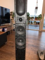
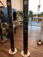
It seems they were discarded as they has suffered which now I understand to be a common problem of cracking rubber speaker surrounds.
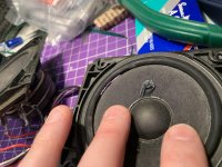
As they were wet, dirty and smelling of fox urine I decided to strip them down, dry out the damp electronics and then wash the contaminated parts. Turns out the scent of a fox is very tricky to get rid of, something I hadn't anticipated.
Once dried with a hair dryer it was time to move onto testing them.
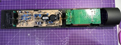
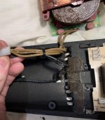
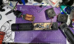
When launched in 1992 these speakers retailed for $2500 which is an incredible amount of money considering, although they seem to be well made using a cast aluminium chassis which doubles as a heatsink, fibre reinforced composite for the driver and tweeter housing and branded components for example Hitachi wires and Elna caps.
Both speakers are working so I ordered some replacement rubber speaker surrounds from Audiofriends in the Netherlands, the kit includes 4x surrounds, glue and fitting instructions for £24 including delivery, very reasonable. These replacement rubber surrounds apparently also add a little extra bass, I’m not sure how though.
I then proceeded to remove the old surrounds and adhesive in preparation.
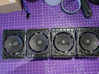
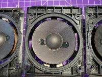
Having used Beolab 8000’s in the past I’m fully prepared to be underwhelmed by these speakers, however in London space is a premium and these speakers would would work well as bedroom units given the small footprint and active design.
I have a Bluetooth 5.0 module lying around and noticed that it would fit perfectly attached to the back of the MOSFET unit, the screws are correctly spaced and the threads are the right diameter with some spacers to move the board off the back of the MOSFET unit and with longer screws to accommodate the spacer it should fit well (could the switching frequency of the mosfets effect Bluetooth?..
There’s a few challenges to overcome, one will be finding a 12v - 24v DC supply from the board, ideally I’d like to fit the module with minimal hackery so as to keep the speakers looking stock externally.
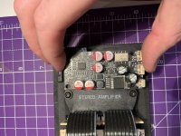
These Bluetooth modules have an auto sensing line-in input meaning the aux input on the bottom of the unit can be retained keeping inline with my minimal hacking ethos.
The second somewhat easier challenge is routing the second channel of the Bluetooth DAC module to the other speaker whilst also retaining the aux input. As I understand it these speakers can be daisy chained using the B&O power link connector (a proprietary DIN based connection) but this only works when a B&O preamp with a power link connection is used. On the bottom of each speaker is a toggle switch which allows setting to left or right depending on the positioning of the speaker within the room.
When using something other than a B&O source with Powerlink, each speaker would then have to be sent one channel each using an single channel RCA, as each speaker has a a single RCA aux input. For example the left speaker is fed a the Left channel using an RCA cable and the right speaker is fed the Right channel using an RCA cable.
My assumption is that it would be tricky to utilise the Powerlink connection as my interconnect whilst still keeping it working as a powerlink connection as it’s proprietary. As I don’t have any B&O sources and don’t intend to I guess I can remove the connections on the internal amp side of it and just use it as a DIN based interconnect assuming I make modifications to the other speaker.
My question is, what would be maximum cable run I could use to send that line level signal from the tiny Bluetooth DAC module to the other speaker? I presume a few meters will be fine.
Whilst looking inside the speakers I noticed a severe lack of damping material. My knowledge on this area is limited but I suspect due to the small internal volume of these speakers (3 litres) any extra damping would reduce the internal volume too much, hampering the already limited bass performance. Would adding something like thin layers of basotect (cut up magic eraser) instead of the grey foam already in there improve things at all. I’m not sure what I’m looking to improve to be honest, maybe reduce any resonance of the aluminium housing?
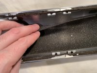
Lastly I’ve ordered some adhesive backed foam tape to replace the horrible disintegrated stuff in there. Apparently a known fault with these speakers and beolab 8000’s is something coined as foam rot.
One had been kicked over and lightly urinated on by a local fox and considering where I live London I was surprised this was the limit of neighbourhood interference. Rule of thumb around here is, if its not bolted down its stripped for parts and then what’s left is set alight, I suspect the rain that day slowed proceedings.


It seems they were discarded as they has suffered which now I understand to be a common problem of cracking rubber speaker surrounds.

As they were wet, dirty and smelling of fox urine I decided to strip them down, dry out the damp electronics and then wash the contaminated parts. Turns out the scent of a fox is very tricky to get rid of, something I hadn't anticipated.
Once dried with a hair dryer it was time to move onto testing them.


When launched in 1992 these speakers retailed for $2500 which is an incredible amount of money considering, although they seem to be well made using a cast aluminium chassis which doubles as a heatsink, fibre reinforced composite for the driver and tweeter housing and branded components for example Hitachi wires and Elna caps.
Both speakers are working so I ordered some replacement rubber speaker surrounds from Audiofriends in the Netherlands, the kit includes 4x surrounds, glue and fitting instructions for £24 including delivery, very reasonable. These replacement rubber surrounds apparently also add a little extra bass, I’m not sure how though.
I then proceeded to remove the old surrounds and adhesive in preparation.


Having used Beolab 8000’s in the past I’m fully prepared to be underwhelmed by these speakers, however in London space is a premium and these speakers would would work well as bedroom units given the small footprint and active design.
I have a Bluetooth 5.0 module lying around and noticed that it would fit perfectly attached to the back of the MOSFET unit, the screws are correctly spaced and the threads are the right diameter with some spacers to move the board off the back of the MOSFET unit and with longer screws to accommodate the spacer it should fit well (could the switching frequency of the mosfets effect Bluetooth?..
There’s a few challenges to overcome, one will be finding a 12v - 24v DC supply from the board, ideally I’d like to fit the module with minimal hackery so as to keep the speakers looking stock externally.

These Bluetooth modules have an auto sensing line-in input meaning the aux input on the bottom of the unit can be retained keeping inline with my minimal hacking ethos.
The second somewhat easier challenge is routing the second channel of the Bluetooth DAC module to the other speaker whilst also retaining the aux input. As I understand it these speakers can be daisy chained using the B&O power link connector (a proprietary DIN based connection) but this only works when a B&O preamp with a power link connection is used. On the bottom of each speaker is a toggle switch which allows setting to left or right depending on the positioning of the speaker within the room.
When using something other than a B&O source with Powerlink, each speaker would then have to be sent one channel each using an single channel RCA, as each speaker has a a single RCA aux input. For example the left speaker is fed a the Left channel using an RCA cable and the right speaker is fed the Right channel using an RCA cable.
My assumption is that it would be tricky to utilise the Powerlink connection as my interconnect whilst still keeping it working as a powerlink connection as it’s proprietary. As I don’t have any B&O sources and don’t intend to I guess I can remove the connections on the internal amp side of it and just use it as a DIN based interconnect assuming I make modifications to the other speaker.
My question is, what would be maximum cable run I could use to send that line level signal from the tiny Bluetooth DAC module to the other speaker? I presume a few meters will be fine.
Whilst looking inside the speakers I noticed a severe lack of damping material. My knowledge on this area is limited but I suspect due to the small internal volume of these speakers (3 litres) any extra damping would reduce the internal volume too much, hampering the already limited bass performance. Would adding something like thin layers of basotect (cut up magic eraser) instead of the grey foam already in there improve things at all. I’m not sure what I’m looking to improve to be honest, maybe reduce any resonance of the aluminium housing?

Lastly I’ve ordered some adhesive backed foam tape to replace the horrible disintegrated stuff in there. Apparently a known fault with these speakers and beolab 8000’s is something coined as foam rot.
Last edited:
Few meters should be fine. Servicemanuals are online to find taplocations for power.
But first make sure you do not take phonecalls or get interrupted long enough to mess up glueing the surrounds 🙂
But first make sure you do not take phonecalls or get interrupted long enough to mess up glueing the surrounds 🙂
If you can find a 3.7 to 5 volt sorce Amazon sell a " SODIAL Bluetooth Decoder Modified Bluetooth 4.1 Circuit Board.. " currently £2.79p. It only has an output, no auto sensing audio in. I have used it with a jack to rca lead ( it also has provision for solder conections ) , the lead is a couple on meters long and works fine. I added some stiffening caps on the power in, but I can't say I heard an improvement, it sounds pretty decent though.
Few meters should be fine. Servicemanuals are online to find taplocations for power.
But first make sure you do not take phonecalls or get interrupted long enough to mess up glueing the surrounds 🙂
This is super helpful irribeo, I hadn't thought to look for the service manuals. I've had a look at one this morning and they are very comprehensive and should certainly help, so thank you.
Regarding the gluing of the surrounds, yes that's good advice to not be distracted.
Nice job! Reminds me of the pair I have standing around in the basement...
Thanks, do you have a project in mind for them?
If you can find a 3.7 to 5 volt sorce Amazon sell a " SODIAL Bluetooth Decoder Modified Bluetooth 4.1 Circuit Board.. " currently £2.79p. It only has an output, no auto sensing audio in. I have used it with a jack to rca lead ( it also has provision for solder conections ) , the lead is a couple on meters long and works fine. I added some stiffening caps on the power in, but I can't say I heard an improvement, it sounds pretty decent though.
Thanks for the recommendation Cracked case. At a quarter of the price of the one I have it certainly seems like good value. Having used older Bluetooth technology like 4.1 for example I can certainly here a a difference in quality, maybe that was the implementation though.
I find the Bluetooth module I have to be really good in terms of sound quality, how do you find the "SODIAL Bluetooth Decoder Modified Bluetooth 4.1 Circuit Board" compares to Bluetooth 5.0?
For reference for anybody interested here's a link to the module:
Ebay link
Unfortunately I have only listened to Bluetooth through the SODIAL, so can't compare it with 5.0. Another idea would be to use a " Digital Amplifier Board Accessory ...." also from Amazon ( currently £ 12.56p - free delivery ), listed dimensions 84x52x24mm, it runs of between 5 and 27 volts, and uses Bluetooth 5.0 and has auto sensing line in. I find class d amplification much better than AB, a cheep amp sounding much better than my old nad 3020, I wonder if a class d amp would improve the BnOs. It's a shame that they don't still make cool CD players.
I mainly want to get them back into condition (surround replacement), measure the acoustic output and plan to use the analog in. With a good line driver unbalanced lines can have some meters. Your BT-adaptation sure is compelling though, I'm only concerned about oversteering the input too easily.Thanks, do you have a project in mind for them?
...there are a dozen small (old)electrolytics in signalpath (and feedback), especially those in treble signalpath I would replace for film(values on pcb most of times different from manual)... signal is being filtered with ceramic smd's a couple of times, values most of times higher than specced, replaced by cog in values suggested by Sanyo eg helps to bring life...when feeling brave the 4558's can be replaced by eg 1642's 🙂
Unfortunately I have only listened to Bluetooth through the SODIAL, so can't compare it with 5.0. Another idea would be to use a " Digital Amplifier Board Accessory ...." also from Amazon ( currently £ 12.56p - free delivery ), listed dimensions 84x52x24mm, it runs of between 5 and 27 volts, and uses Bluetooth 5.0 and has auto sensing line in. I find class d amplification much better than AB, a cheep amp sounding much better than my old nad 3020, I wonder if a class d amp would improve the BnOs. It's a shame that they don't still make cool CD players.
I did briefly think about "what if Class D" but then realised that the amp boards in there probably have some kind of DSP or digital crossover tech. From looking at the service manual it mentions an active crossover and I suspect reengineering something like this would be tricky, personally I wouldn't know where to start, also I think it would be a lengthy and costly process.
I mainly want to get them back into condition (surround replacement), measure the acoustic output and plan to use the analog in. With a good line driver unbalanced lines can have some meters. Your BT-adaptation sure is compelling though, I'm only concerned about oversteering the input too easily.
I was thinking of using these as rear speakers too, however I don't have an AV processer yet. I really want to get the Okto Dac 8 pro and create an AV processor maybe with a NUC or ideally with a PI as I think that would be cool, however there are hardware limitations surrounding the latter.
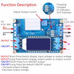
So far I'm not having much like finding a DC 12v source from the board so I need to work out how to make it work. The challenge is the amps have an auto-on circuit which means in standby most of the board isn't producing voltage. I need a constant 12v - 24v supply so the when I connect to the Bluetooth board the line out signal wakes up the rest of the amp. From my previous testing I found a 12v signal in the Bluetooth module performed best, I noticed as the voltage increased it appeared to add noise, however maybe this is a function of the power supply I was using - laptop brick into a cheap DC DC step down power supply.
...there are a dozen small (old)electrolytics in signalpath (and feedback), especially those in treble signalpath I would replace for film(values on pcb most of times different from manual)... signal is being filtered with ceramic smd's a couple of times, values most of times higher than specced, replaced by cog in values suggested by Sanyo eg helps to bring life...when feeling brave the 4558's can be replaced by eg 1642's 🙂
This is very interesting Irribeo. When you say "values on PCB different from service manual" do you mean the service manual is like the reference design for example, but they downgraded the parts at production? And to clarify would you recommend replacing the parts with Film Capacitors based on the values in the service manual, or use the values on the parts on the PCB as reference?
Regarding the statement "values most of times higher than specced" do you again mean at production/manufacture they have deviated from the values in the service manual?
You have really intrigued me now...Have you made these modifications yourself? I'm definitely up for swapping out parts if they will improve the sound. Thanks for sharing your knowledge.
For the electrolytics in signalpath(and feedback) you use values like on pcb (but film🙂). The ceramic smd's are supposed to filter inputsignal very high frequencies, eg frequencies above 100kHz. If you measure them and compare to service manual you will find that those on pcb are larger values(filter lower (high) frequencies. If you compare Sanyo advice for stk implementation you'll find those values are lower than B&O servicemanual, so you have 3 gradations of being carefull or over-carefull. On other places online you will find posts about removing those ceramics completely and positive reviews. I suggest using the Sanyo values in a better quality, cog. But placing a chinese pcb inside the cabinet might be what B&O anticipated thus increasing the values to eliminate problems.
Some values on pcb could be wrong by mistake, some parts could be omitted by mistake, but values could be changed and not every change leads to an updated manual. You have to decide/investigate if so (same for polarity differences between parts on pcb and pcb polarity marker, could be intentionally, could be a mistake, not every mistake results in a product not working). But I do not remember polarity issues with lab6000 I have seen.
Speaker is active, opamps(4558 mostly) are used to filter and shape signal, yes like an internal dsp and an internal basslimiter to reduce bass when increasing volume, to keep small speakers in the speakercabinet and not burning outside lol. When surrounds are glued and you test speaker with bass you will find the small pipe pumps a lot of air through the reflexport on top (the sticker on the port is to change fase of the portfibrations, with sticker they are in phase). If surround isn't glued ok, not airtight, you will clearly hear the noise the leak(s) make, sounds a little like a blown speaker, not just on heavy bass but also on violins.
Standby powersupply is permanent, I guess that is same powersupply for B&O own signal sensing on the cinch input? The powerlink input is switched on by a triggerlead voltage, so external, not signal switched.
Yes I have done replacements as posted, to speakers brought to me
I believe these are power switched on the signal inputs too. Mine do anyway. And the 6000 indeed have some level-dependent loudness built in too (like loudness has to be implemented btw). Nice feedback irribeo, thx!
Maybe only poweramp power is switched on/off ?? I never looked at it really. I do recall 14 pieces off the 4558 opamps and some other types used around the basslimiting(ABL) and a lot of ecaps in signalpath(s)mind you most around the 4558's are film already
For the electrolytics in signalpath(and feedback) you use values like on pcb (but film🙂). The ceramic smd's are supposed to filter inputsignal very high frequencies, eg frequencies above 100kHz. If you measure them and compare to service manual you will find that those on pcb are larger values(filter lower (high) frequencies. If you compare Sanyo advice for stk implementation you'll find those values are lower than B&O servicemanual, so you have 3 gradations of being carefull or over-carefull. On other places online you will find posts about removing those ceramics completely and positive reviews. I suggest using the Sanyo values in a better quality, cog. But placing a chinese pcb inside the cabinet might be what B&O anticipated thus increasing the values to eliminate problems.
Some values on pcb could be wrong by mistake, some parts could be omitted by mistake, but values could be changed and not every change leads to an updated manual. You have to decide/investigate if so (same for polarity differences between parts on pcb and pcb polarity marker, could be intentionally, could be a mistake, not every mistake results in a product not working). But I do not remember polarity issues with lab6000 I have seen.
Speaker is active, opamps(4558 mostly) are used to filter and shape signal, yes like an internal dsp and an internal basslimiter to reduce bass when increasing volume, to keep small speakers in the speakercabinet and not burning outside lol. When surrounds are glued and you test speaker with bass you will find the small pipe pumps a lot of air through the reflexport on top (the sticker on the port is to change fase of the portfibrations, with sticker they are in phase). If surround isn't glued ok, not airtight, you will clearly hear the noise the leak(s) make, sounds a little like a blown speaker, not just on heavy bass but also on violins.
Standby powersupply is permanent, I guess that is same powersupply for B&O own signal sensing on the cinch input? The powerlink input is switched on by a triggerlead voltage, so external, not signal switched.
Yes I have done replacements as posted, to speakers brought to me
Thanks for sharing for sharing all this info, much appreciated. I think I will go ahead and try and upgrade the components based on your information (well I will at least try). This is quite technical for me so I will have to learn quite a lot.
I assume that considering you have done this yourself that its a worthwhile exercise.
Glueing the surrounds so the speakers can play without noises is main thing, obviously. After listening to them for a while you can decide to replace some parts.
The adhesive foam tape and magic erasers arrived the other day and I managed to get some time to fit the new tape and cut the erasers up into 6mm slivers to line the housing. I made a rough and ready cutting jig out of left over foam core. Seems they are easy to slice with a sharp knife:
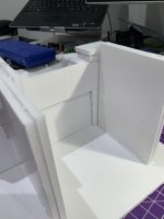
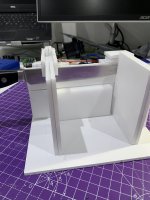
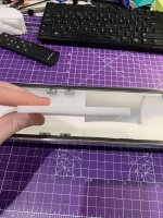
Seems two slivers fit into the housing side-by-side perfectly, however I doubt this mod makes much difference to the sound. At least it replaces the old disintegrated foam in there though.
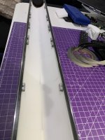
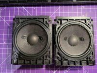
Then glued the surrounds to the housings, I used a liberal amount of glue on the housings as they had a stippled effect moulded into the plastic, I was concerned this would cause air gaps as the glue dried. I fitted 2 of the speakers into one cabinet to test and they actually sound alright, I’m suprised really, they will make ideal bedroom speakers or rear surround speakers.
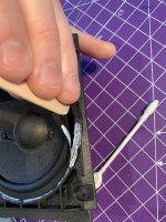
The next task will be start working out what parts to replace on the boards as per irrebo’s suggestions.


Seems two slivers fit into the housing side-by-side perfectly, however I doubt this mod makes much difference to the sound. At least it replaces the old disintegrated foam in there though.

Then glued the surrounds to the housings, I used a liberal amount of glue on the housings as they had a stippled effect moulded into the plastic, I was concerned this would cause air gaps as the glue dried. I fitted 2 of the speakers into one cabinet to test and they actually sound alright, I’m suprised really, they will make ideal bedroom speakers or rear surround speakers.


The next task will be start working out what parts to replace on the boards as per irrebo’s suggestions.
- Home
- Loudspeakers
- Multi-Way
- Beolab 6000 - repair, Bluetooth conversion and damping upgrade - Basotect?