Hey Great Folks,
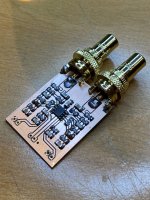
I have designed a miniature PCB for OPA1656 amp (schematics from it's datasheet) I wanted to build into my new old Thorens TD166, so here it is if anyone is interested in similar endeavor.

Have a great New Year ahead.
I have designed a miniature PCB for OPA1656 amp (schematics from it's datasheet) I wanted to build into my new old Thorens TD166, so here it is if anyone is interested in similar endeavor.
Have a great New Year ahead.
Last edited:
OPA1656 is some 2.5x noisier than e.g. OPA627 at 10Hz.
Any maybe you can consider Panasonic ECHU for the caps.
The 100µ will be difficult .....
Nice PCB, BTW.
Happy New Year,
Patrick
Any maybe you can consider Panasonic ECHU for the caps.
The 100µ will be difficult .....
Nice PCB, BTW.
Happy New Year,
Patrick
JRA had some stability problems with that circuit, see this thread:
https://www.diyaudio.com/community/threads/opa1656-phono-preamp-split-from-opa1656-thread.377331/
See also post #106.
https://www.diyaudio.com/community/threads/opa1656-phono-preamp-split-from-opa1656-thread.377331/
See also post #106.
With a proto board like that, I am somehow not surprised 🙂
Mine is already up and running, no stability issues. But thanks for pointing out, I will run some additional checks.
Mine is already up and running, no stability issues. But thanks for pointing out, I will run some additional checks.
JRA has a shorting switch in the turntable that shorts the cartridge just before the arm is lifted. The stability issues only occured when the switch shorted the cartridge, the cable to the amplifier then acted as a transmission line resonator that got undamped by the amplifier.
No joy without good old thump when the stulys hits the vinyl 🙂JRA has a shorting switch in the turntable that shorts the cartridge just before the arm is lifted. The stability issues only occured when the switch shorted the cartridge, the cable to the amplifier then acted as a transmission line resonator that got undamped by the amplifier.
What kind of resistors and caps did you use? I've stuck to thin-film resistors and PPS caps for my SMT phono preamps.Hey Great Folks,
I have designed a miniature PCB for OPA1656 amp (schematics from it's datasheet) I wanted to build into my new old Thorens TD166, so here it is if anyone is interested in similar endeavor.
NP0/COG is probably OK for the filter capacitors, but I agree with EUVL that the 100 uF capacitors will be "difficult". To get them in the size shown, they would have to be something like X7R or X5R (hopefully not Z5U or Y5V), but that will add distortion. Bi-polar elecrolytic capacitors would be better, but larger.
What is the reason for selecting the OPA1656? A fine op-amp, but you will probably get around half the noise with an OPA1642.
What is the reason for selecting the OPA1656? A fine op-amp, but you will probably get around half the noise with an OPA1642.
I'd be cautious about using smt PPS caps in the RIAA network -- they shift as much as 5% when going though soldering.
They are available with 2% tolerance in SMT, fully characterized for reflow soldering, so you are being pessimistic - PPS is one of the highest temperature plastic film dielectrics (both PS and PP melt at too low a temperature for SMT). 1% PPS through-hole caps are also a thing.I'd be cautious about using smt PPS caps in the RIAA network -- they shift as much as 5% when going though soldering.
PPS is low distortion and thermally stable enough for SMT. Of the available options is perhaps the best (though for very small values of capacitance C0G/NP0 ceramics may available).
I'd check, for example, the Wima SMD-PPS datasheet. "The capacitance recovery accuracy to be expected with careful processing is within a scope of
Delta-C/C <= 5 %."
Delta-C/C <= 5 %."
Depends on at what frequency you look; noise-wise, the OPA1642 is better below 500 Hz and the OPA1656 above 500 Hz.What is the reason for selecting the OPA1656? A fine op-amp, but you will probably get around half the noise with an OPA1642.
Assuming the voltage noise has a white and a 1/f part, which seems to be correct, for the total RIAA- and A-weighted noise, what matters is the noise around 1162 Hz. That is, when you do the math, you find that 1 nV/sqrt(Hz) of 1/f noise at 1162 Hz has the same impact on the integrated RIAA- and A-weighted noise as 1 nV/sqrt(Hz) of white noise. Besides, when the cartridge inductance is high, the 47 kohm input termination resistor contributes more to the RIAA- and A-weighted noise than either op-amp (and when you play a record, record surface noise dominates completely).
When you care more about the unweighted noise, that is, RIAA and 20 Hz to 20 kHz ideal bandpass weighted, then that 1162 Hz turns into 85.86 Hz, so the OPA1642 then wins. For RIAA and ITU-R 468 weighting, it's 2897 Hz.
Last edited:
You mean this datasheet? https://www.wima.de/wp-content/uploads/media/e_WIMA_SMD_PPS.pdfI'd check, for example, the Wima SMD-PPS datasheet. "The capacitance recovery accuracy to be expected with careful processing is within a scope of
Delta-C/C <= 5 %."
Those are 20% and 10% caps, not really suitable for filtering at those tolerances. Panasonic do 2% PPS SMT caps, ECHU(X): https://docs.rs-online.com/72de/0900766b815c4ec9.pdf
It is correct that with A-weighting the OPA1656 has a slight advantage. Over a 20 kHz BW my simulation shows a noise difference of 0.4 dB, using A-weighting and a cartridge model obtained here: cartridge model
For fun I also simulated the circuit with a "state of the art op-amp" I used for a design (around 40 years ago). It was the LF356. The noise was a lot higher, like 13.5 dB higher. So I should probably try out the OPA1641 or OPA1655 in my old design. I haven't used it for many years, but might try it out with a Technics SL-23 that I am in the process of restoring (waiting for a new belt, the old one has disintegrated).
Are PPS capacitors better than NP0 in any way? It seems like NP0 capacitors are actually smaller than PPS capacitors, e.g., a 220 nF/50 V 2% is available in 1206. You can also get a 470 nF/25 V in 1206 (at least in 5%).
The capacitor values used in this design can be even smaller (except for the 100 uF of course).
Mark, yes, that's the datasheet, and yes, the WIMA caps are not 2% initial tolerance, but the materials and construction are essentially identical. Thus I'd take WIMA's comments to heart for both brands (Panasonic doesn't specifically call this out in their supporting documentation but have enough caveats about 'reliability' that I believe the same behaviors are to be expected). I would be cautious about how soldering is done -- hand soldering is risky per both companies and a home reflow oven may not be sufficiently well-controlled to keep within the tight temperature limits.
For any caps in precision applications (EQ and filter circuits) for DIY, I would stay with through-hole capacitors that can be soldered after everything else on the board and done without transferring much heat to their innards. Experience over many years and many projects/applications, both commercial/industrial and hobby, is the basis for my conclusions.
Yes, PPS has higher temperature rating than other common films making them (barely) adequate for (well-controlled) SMT reflow processes, but that doesn't come without a number of significant caveats.
They're getting smaller all the time. The last time I looked, which is about four or five years ago, 1812 was still the most common footprint for 220 nF NP0, and 1210 for 100 nF NP0.Are PPS capacitors better than NP0 in any way? It seems like NP0 capacitors are actually smaller than PPS capacitors, e.g., a 220 nF/50 V 2% is available in 1206. You can also get a 470 nF/25 V in 1206 (at least in 5%).
The capacitor values used in this design can be even smaller (except for the 100 uF of course).
All XR7 SMD 1206 caps, 1206 metal film resistors.What kind of resistors and caps did you use? I've stuck to thin-film resistors and PPS caps for my SMT phono preamps.
- Home
- Source & Line
- Analogue Source
- OPA1656 RIAA PreAmp