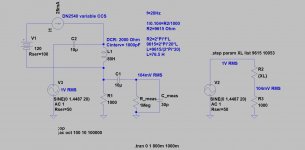
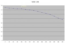
Laminated core output transformers are nonlinear. Due to the shape of the B-H curve, the primary inductance at low signal level is much lower than at the nominal max. output level. Let's keep below saturation.
The change of primary inductance has effect on low frequency cutoff of the whole amplifier. Global negative feedback could compensate it in some extent, but let's disregard it for now.
How audible is the level dependent change of low frequency cutoff? I mean it could happen that the cutoff frequency is as high as 100Hz @1mW output level, but it is 20Hz @1W output level and 15Hz @10W. Psychoacoustically, the human hearing threshold of low frequencies is higher at low level, so perhaps this effect of cutoff shift is not audible? Or is it?
Last edited:
Assume we have an EL84 SE amplifier. The frequency response at low end should be much better at 3 W than at 1 W.the primary inductance at low signal level is much lower than at the nominal max. output level.
Is it really ?
Perhaps there is not so much difference between 3W and 1W. But there could be between 3W and 3mW. At 3W the magnetic induction curve is on the linear region, and it is much steeper than at 3mW power output, I suppose. It might be different at a SE amplifier with an air gapped output transformer, though. I was thinking about the push-pull case.
Variation of inductance from core permeability change causes changes in magnetizing current, but does not directly block signal passage. Plate resistance is mostly to blame, and primary winding resistance too. The plate R can be fixed with local voltage N Fdbk. The primary winding resistance can be fixed (also plate R optionally) using positive current feedback from the output tube cathode(s) back to the driver stage.
Just a low R value current sampling resistor below the output tube(s) cathode, then a high value resistor(s) back to the driver tube cathode(s), and a bias resistor below the driver cathode(s). This produces a negative resistance effect, which can cancel primary winding resistance, and optionally plate R too. (plate R varies with current, so the average plate R in the class A region of class AB only, being careful not to end up with extra negative R in the class B regions). Depends on adjustment of the positive Fdbk resistor(s) as to how much neg. resistance is developed.
Essentially, the current sense inserts more drive into the driver stage to cover the resistive losses in the OT, from the sensed current, and optionally the output tube plate R. Leaving just the desired signal to be transferred to the OT secondary after the R losses are incurred. This is mentioned in the RDH4 on page 354-355. With references dating to 1950. In addition there is US Patent US4614914 (1986) discussing removing primary resistance.
You do not want to additionally (here at least) remove the OT secondary R effects, since magnetizing current does not pass thru that section, while the sensing R picks up magnetizing current. (it would be putting an anti-magnetizing current correction in where not needed) The secondary can be used for a separate impedance modifying loop if wanted, ( was done actually, Electrovoice damping control )
Last edited:
While most output transformers show a change in inductance with a change in DC flowing in the primary not all transformers have this. VTV (Vacuum Tube Valley) issue #3 has a test of different manufacturer's OPT for the 300B.
In any case I regard the drop off much of a moot point as our ears react differently at different sound levels - the ear loudness curves pioneered by Fletcher and Munson are showing this. www.sengpielaudio.com/Acoustics226-2003.pdf
In any case I regard the drop off much of a moot point as our ears react differently at different sound levels - the ear loudness curves pioneered by Fletcher and Munson are showing this. www.sengpielaudio.com/Acoustics226-2003.pdf
The whole idea is false , the inductance is not much lower at low level ... I wish to measure 25H with a LCR bridge ( very low sine level ) and to have 100H when the amp is giving some power 

I want to measure the inductance at near full power. The turns ratio of my transformer is 20:1. The mains voltage over here is 230V. So what if I connect it to the mains, and load the secondary with a 50 Watt car light bulb? And then measure the phase shift of the primary current somehow, and calculate the inductive reactance from it? Do you recommend any alternative measuring method?Why don't you simply measure it and see for yourself?
Cheers
Ian
Sorry, I meant why don't you measure the frequency response of the amp as 1mW, 1W and so on to see if the response droops at low frequencies at low levels. Obviously you would need to disconnect any NFB from the transformer secondary but you are not worried about distortion.I want to measure the inductance at near full power. The turns ratio of my transformer is 20:1. The mains voltage over here is 230V. So what if I connect it to the mains, and load the secondary with a 50 Watt car light bulb? And then measure the phase shift of the primary current somehow, and calculate the inductive reactance from it? Do you recommend any alternative measuring method?
Cheers
Ian
- Home
- Amplifiers
- Tubes / Valves
- Output transformer level dependent low frequency response

