Coverage of assemblage of Lottery amp for my dear Friend, way of paying back for valuable help he gave in some of my endeavors
He's extraordinary busy in last several months, so ......
Amp No. 122, member tunasto here, Vinko at Baby DiyA
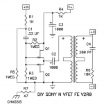
Let's start with schematics - I like when schematics are present
He's extraordinary busy in last several months, so ......
Amp No. 122, member tunasto here, Vinko at Baby DiyA
Let's start with schematics - I like when schematics are present
Attachments


Last edited:
While at schematics, let's cover few things ( I already posted in origin thread about this amp), so let's repeat:
well, I'm always amused studying Papa's schematics, from any imaginable reason .... mistakes being one of them
original, drawing mistake marked, mistake fixed, simple remedy for better AntiBigBadaBoom at speaker out; there is no mistake at Papa's pcb, it is just on drawing
now - last schm - in this moment already tried and proven, results are:
edited delay circ is working flawlessly - no visible move of cone neither at power On nor power Off
only if you are powering it Off reluctantly, slowly operating the switch , there is movement of cone, but slow and gentle - and even that one is not audible
same behavior when leaving power switch ON, and doing power operation with mains cable of switcher - Nada during power On, gentle roll of cone with powering Off
will post plenty of pics and some text, in separate thread
maybe next evening
and yes, really dunno how delay circ operated in original, didn't tried it at all; but I'm used to change Papathings just for sport - hard to make it better, easy to make it in different way
Attachments


OK; thermal issues
some facts:
some facts:
- T bars came in Papa's arrangement, with approx 4mm Dia holes
- TO3 isolator pads are silicone thingies, I don't like those above 15W or so per device; gone for Mica + quality goop
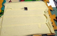
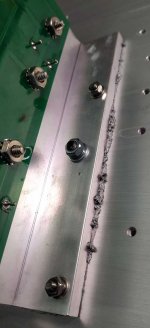
- T bar is having bowed side which is going to meet heatsink; see sketch; some lapping - water-sand paper on thick glass is problem solver
- heatsink is bowed as all extruded heatsink of this profile are bowed; see sketch; no problem when you arrange adequate force with screws - not the case in this case; will rectify that
Attachments


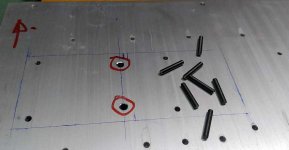
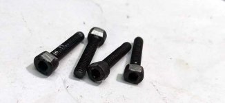
solving thermal issues; see pics, pretty much self-explanatory
whoever did arrange with Modushop guys assembly with M3 screws is not having enough mileage with all things mechanical/thermal; not blaming a guy at all, I know that this wasn't operation made by professionals and outcome is still extraordinary
that's exact reason why I'm posting this, to help Greedy Boyz in proper finishing and to feed my own OCD
fact is -these 4pcs of M3 screws needed to be M4 and additional 2pcs of M4 are necessary
only that way , with lapped T Bar, there is enough squeezing force at disposal to get rid of air gap between T Bar and heatsink
Attachments
-
 2.jpg59.3 KB · Views: 308
 -
 3.jpg70.5 KB · Views: 307
 -
 4.jpg59.6 KB · Views: 302
 -
 5.jpg66 KB · Views: 304
 -
 6.jpg67.4 KB · Views: 303
 -
 6a.jpg74.6 KB · Views: 291
 -
 7.jpg35.1 KB · Views: 301
 -
 8.jpg51.1 KB · Views: 295
 -
 9.jpg99.5 KB · Views: 295
 -
 10.jpg27.1 KB · Views: 292
 -
 11.jpg27.2 KB · Views: 287
 -
 12.jpg34.7 KB · Views: 281
 -
 13.jpg59.8 KB · Views: 283
 -
 15.jpg54.5 KB · Views: 280
 -
 14.jpg104.6 KB · Views: 304
Still in mechanical realm, sort of
Again post-Pa dealing gone wrong - Pa did arrange 2 pole switch, while hole on back side is for one pole, one pole in kit;
Again no blame from my side ; I did enough mistakes that I know from where they are invoked, rest of life is not enough to learn how to prevent them
I had a bag of proper 2 pole switches
paper masking tape, calipers, files, patience
Attachments


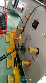
Still on back side of amp
Mean Well switcher PSU is of good quality, but I don't like flimsiness of DC connector, neither male nor female one
Good ole 5-pin XLR is certainly better; I would like Calt Stecker being on cable, Heiss Stecker being on amp, but didn't had Heiss one ....... anyway , I did stay with original topology - Heiss Stecker on cable
superblingy drill and edge reamer, no need to be overly precise, XLR is covering all
I didn't even hop to my vertical drill, done it with hand-accu one
useful tip for soldering pin-equipped connectors - always mary male one with female one - no bending of pins in plastic, due to heat
Attachments


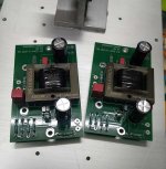
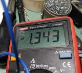
Delay circ tweaking
Again, self explanatory
Again, self explanatory
Attachments
-
 1.jpg58.3 KB · Views: 287
 -
 1a.jpg75.5 KB · Views: 276
 -
 2.jpg201.6 KB · Views: 263
 -
 3.jpg140.7 KB · Views: 249
 -
 4.jpg157.9 KB · Views: 254
 -
 5.jpg62.5 KB · Views: 251
 -
 6.jpg123.3 KB · Views: 249
 -
 7.jpg66.5 KB · Views: 254
 -
 8.jpg115.8 KB · Views: 260
 -
 9.jpg189.5 KB · Views: 267
 -
 9a.jpg190.1 KB · Views: 258
 -
 10.jpg156.3 KB · Views: 275
 -
 11.jpg136.5 KB · Views: 279
Rest of pics
Observe - there are some trick which can make your life easier:
-Cone head temporary screws ( aligning, no scratches round holes)
-align brackets with back side of heatsinks, no warping of back plate in that case
dunno - I did forgot something for sure , but you'll ask; it's not Rocket Science anyway
there are probably few redundant pics, but - hey - web space is cheap nowadays
Observe - there are some trick which can make your life easier:
-Cone head temporary screws ( aligning, no scratches round holes)
-align brackets with back side of heatsinks, no warping of back plate in that case
- headless screws for front plate; how to unscrew and orient bottom to mount washers and nuts and tighten them
- wiring done with one heatsink, bottom and back plate screwed together; then mounting second heatsink, soldering wires, then mounting front
- one or two pads are close to screw nuts; marked on pics; either use plastic washers or metric screws/nuts ( smaller than enclosed ones) or be brave as MZM - I did bend integral star washers, was stubborn to use Papahardware
dunno - I did forgot something for sure , but you'll ask; it's not Rocket Science anyway
there are probably few redundant pics, but - hey - web space is cheap nowadays
Attachments
-
 IMG_20220428_165828.jpg82.8 KB · Views: 346
 -
 IMG_20220428_165908.jpg82.1 KB · Views: 344
 -
 IMG_20220428_165912.jpg69.4 KB · Views: 318
 -
 IMG_20220428_170853.jpg61.8 KB · Views: 313
 -
 IMG_20220428_170901.jpg85.3 KB · Views: 1,153
 -
 IMG_20220428_202849.jpg93.9 KB · Views: 287
 -
 IMG_20220428_202903.jpg70.4 KB · Views: 289
 -
 IMG_20220429_215659.jpg43.6 KB · Views: 284
 -
 IMG_20220429_215709.jpg44.1 KB · Views: 282
 -
 IMG_20220429_220949.jpg43 KB · Views: 289
 -
 IMG_20220429_220956.jpg53.4 KB · Views: 294
 -
 IMG_20220429_221157.jpg118.3 KB · Views: 308
 -
 IMG_20220430_180547.jpg78.4 KB · Views: 314
 -
 IMG_20220504_193529.jpg57.3 KB · Views: 279
 -
 IMG_20220504_193534.jpg52.4 KB · Views: 347
.........
Attachments
-
 IMG_20220504_193539.jpg52.8 KB · Views: 247
 -
 IMG_20220504_193546.jpg58.8 KB · Views: 233
 -
 IMG_20220504_193552.jpg93 KB · Views: 242
 -
 IMG_20220504_201731.jpg55.1 KB · Views: 246
 -
 IMG_20220504_202703.jpg80.7 KB · Views: 256
 -
 IMG_20220504_214131.jpg116.5 KB · Views: 275
 -
 IMG_20220505_135930.jpg109.1 KB · Views: 283
 -
 IMG_20220505_135939.jpg92.2 KB · Views: 272
 -
 IMG_20220505_135942.jpg142.6 KB · Views: 257
 -
 IMG_20220505_135948.jpg107.8 KB · Views: 267
 -
 IMG_20220505_135958.jpg92.7 KB · Views: 267
 -
 IMG_20220505_140003.jpg73.4 KB · Views: 252
 -
 IMG_20220505_140007.jpg92.7 KB · Views: 243
 -
 IMG_20220505_140014.jpg81.4 KB · Views: 233
 -
 IMG_20220505_140031.jpg60.2 KB · Views: 249
...........
Attachments
-
 IMG_20220505_140036.jpg54.9 KB · Views: 249
 -
 IMG_20220505_140041.jpg85.7 KB · Views: 237
 -
 IMG_20220505_140047.jpg82.9 KB · Views: 233
 -
 IMG_20220505_140544.jpg85.8 KB · Views: 220
 -
 IMG_20220505_140547.jpg56.5 KB · Views: 214
 -
 IMG_20220505_140552.jpg38.6 KB · Views: 236
 -
 IMG_20220505_153254.jpg117.9 KB · Views: 255
 -
 IMG_20220505_153259.jpg115 KB · Views: 261
 -
 IMG_20220505_153308.jpg65.6 KB · Views: 246
 -
 IMG_20220505_153311.jpg71.9 KB · Views: 236
 -
 IMG_20220506_112259.jpg41.9 KB · Views: 224
 -
 IMG_20220506_112303.jpg62.2 KB · Views: 226
 -
 IMG_20220506_112859.jpg58.4 KB · Views: 243
 -
 IMG_20220506_112911.jpg48.7 KB · Views: 239
 -
 IMG_20220506_112903.jpg62.5 KB · Views: 258
.........
Attachments
-
 IMG_20220506_114519.jpg120.8 KB · Views: 309
 -
 IMG_20220506_114742.jpg101.2 KB · Views: 264
 -
 IMG_20220506_114756.jpg44.8 KB · Views: 238
 -
 IMG_20220506_120359.jpg110.3 KB · Views: 232
 -
 IMG_20220506_120421.jpg46.9 KB · Views: 249
 -
 IMG_20220506_121146.jpg99.3 KB · Views: 271
 -
 IMG_20220506_121201.jpg110.4 KB · Views: 269
 -
 IMG_20220506_121836.jpg100.8 KB · Views: 246
 -
 IMG_20220506_121840.jpg105.7 KB · Views: 250
 -
 IMG_20220506_121947.jpg121.1 KB · Views: 252
 -
 IMG_20220506_130345.jpg62.5 KB · Views: 252
 -
 IMG_20220506_130351.jpg37 KB · Views: 256
 -
 IMG_20220506_130404.jpg83.5 KB · Views: 243
 -
 IMG_20220506_130408.jpg52.3 KB · Views: 267
 -
 IMG_20220506_130502.jpg131.8 KB · Views: 298


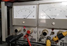
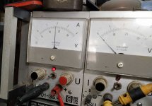
Facts
-PSU 36Vdc
-Iq one channel 1A76, second channel 1A8; was thinking to alter that to 1A6 by the Book, but who cares - more the merrier
-Output node set by the Book - to 14Vdc
-Ambient Temp 20degC
-VFet Case 66degC
-Mos Case 59degC
-T Bar Temp at exact mid between two TO3 50degC
-Heatsink Temp at outer side, between fins, exactly between M4 Allen head screws 44degC
-1R5 at channel pcbs 99degC (Papa is FAB, no clearance)
-3R3 at PSU pcb (ZM is Chicken, 2mm clearance) 88degC
-JFets 44degC
-Switcher case , placed on edge at bench 37degC
-no noise, no hum
-It sings; forgot to take a picture
few more details I forgot:
- ZM is Chicken - 20K multiturn trimpot instead of enclosed 25K FABPa model
-washer + split washer everywhere
-heatshrinking wire ends leads to nicer look; it also increase your Zen
-toss enclosed crimping connectors in trash bin; solder everything; it also increase your Zen
-soldering of sensitive plastic parts - crank station to max, do it fast and efficient - funny but lesser melting of plastic that way
-enclosed nice dome head screws - while M3, having 'Merican Allen key head - who invented that shizo thing - ZM Is not having 'Merican Allen wrenches in appropriate quality, so I can't tighten them properly ..... anyway - stainless steel headless screws and nuts are much better for T Bar tightening ..... even if inadequate
-drilling of 4.2mm holes for additional M4 Allen key screws- sorta mid of T Bar length, use calipers to b precise enough to situate them exactly in between the heatsink fins; drill heatsink first, then mark through these holes points on T Bars
-dissipation of mosfet is 1A8*(14V-(1A8*0R75))=22W77
-dissipation of VFet is (36V-(1R1*1A8)-14V)*1A8=36W04
-summ dissipation per channel , including PSU, is 1A8 x36V=64W8
go figure - 128W of heat for 2x10Wrms
aaaaaaalmost SIT-2 Territory
Last edited:
Those are some excellent mechanical upgrades to the chassis. I may have to disassemble mine to do something similar..

- Home
- Amplifiers
- Pass Labs
- Lottery DIY Sony VFET pt 2 (N-Channel) - assembly by Mighty ZM