i am new on tube, i am considering to add this on my system, but i have a doubt about the voltage supply +- 24v, for what i know tube usually using high voltage. thanks for your reply
Think I would add say 22k bleed resistors down to ground on the outputs as with the heaters cold the output may be at -24V. E88CC is good choice.
With such a low plate to cathode voltage, there may be some grid current.
In that case, a 1 Meg Ohm grid resistor may be an issue.
I hope you are not expecting the input impedance to be 1 Meg Ohm, especially depending on the quality, exact construction, and manufacturer of the ECC88 that you use.
The total voltage is only 48V, including the voltage drop through the resistors.
Take a look at the curves for an ECC88, and for an E88CC. Not very much to be said for less than 90V plate to cathode.
How well it works is tube to tube dependent.
Just my opinions.

Yep did not look at the supply. There's probably only 20-30V from plate to cathode. Maybe change the ratio of R1 to R2 to make the grid-cathode more negative, and make R1 a CCS for linearity.
It will work,sort of, as demonstrated by jcalvarez, not too sure about the purpose.i am new on tube, i am considering to add this on my system, but i have a doubt about the voltage supply +- 24v, for what i know tube usually using high voltage. thanks for your reply
It will add a little distortion, almost undetectable; is that considered an improvement?
Thanks all for your reply, and for jcalvarez for the simulation.
Can you give me the exact value of the resistor r1 and r2?Yep did not look at the supply. There's probably only 20-30V from plate to cathode. Maybe change the ratio of R1 to R2 to make the grid-cathode more negative, and make R1 a CCS for linearity.
My intention is just for a buffer like B1 by mr. Pass, but is expensive and hard to get matched jfet in my country so i consider this buffer. Is that right choice or not? thanksIt will work,sort of, as demonstrated by jcalvarez, not too sure about the purpose.
It will add a little distortion, almost undetectable; is that considered an improvement?
So, i can go for higher voltage using this design?With such a low plate to cathode voltage, there may be some grid current.
In that case, a 1 Meg Ohm grid resistor may be an issue.
I hope you are not expecting the input impedance to be 1 Meg Ohm, especially depending on the quality, exact construction, and manufacturer of the ECC88 that you use.
The total voltage is only 48V, including the voltage drop through the resistors.
Take a look at the curves for an ECC88, and for an E88CC. Not very much to be said for less than 90V plate to cathode.
How well it works is tube to tube dependent.
Just my opinions.
If you want to, just do it.Thanks all for your reply, and for jcalvarez for the simulation.
Can you give me the exact value of the resistor r1 and r2?
My intention is just for a buffer like B1 by mr. Pass, but is expensive and hard to get matched jfet in my country so i consider this buffer. Is that right choice or not? thanks
In any case, JFETs are often used to simulate/replace real tubes; if you have the real thing, just use it 🙂
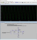
It's fine enough. Plate-loaded it would swing 22Vp-p at 5% THD (heavily 2nd). Cathode-loaded, about the same swing but 20X lower THD, 0.3% @ 22Vp-p. Taking typical level as 1Vrms 3Vp-p, about 1/7th of 0.3% 0.05%THD. If I wanted "less" I would use an op-amp.
That's assuming you can get a real 6DJ8/ECC88 today. I recall some years ago anything that looked like a TV tuner tube was being re-labeled.
That's assuming you can get a real 6DJ8/ECC88 today. I recall some years ago anything that looked like a TV tuner tube was being re-labeled.
Yes.So, i can go for higher voltage using this design?
Actually, if you can double the voltage to +/-48VDC, that would be better.
If you can manage +/-75VDC, that would be nearly ideal.
But what PRR said is also true.
It's fine enough. Plate-loaded it would swing 22Vp-p at 5% THD (heavily 2nd). Cathode-loaded, about the same swing but 20X lower THD, 0.3% @ 22Vp-p. Taking typical level as 1Vrms 3Vp-p, about 1/7th of 0.3% 0.05%THD.
thanks all for your advice, hope you all the best, glad to have this community, i will report back if this project finished.
- Home
- Amplifiers
- Tubes / Valves
- ECC88 as buffer