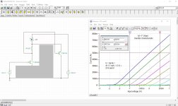
A compound of two 2N7000 enhancement mosfets, showing triode characteristics.
I made these compnds during the summer of '22. They're not optimised to their actual specs, more estimated values for the rest.
Photo's are grayed and partially blurred (idea protection).
Identification in advance is neccessary because the DCA75 does not recognise these qubes.
Once 'fixed' (report from the ct), the leads are swapped from the fixer to the qube, then the dynamic transfer characteristic (Sdyn), then the outpt characteristic with a Rint somewhere in the middle. After restarting the ct, the qube is recognised as a... zener! Hilarious.
µ is low (not optimised), but with these two 2N7000 the yield is: µ = Sd * Ri = 5.2 mA/V * 770 Ω = 4
In preparation:
Is a V-fet an influencer?
I cannot tell.
Mars
I made these compnds during the summer of '22. They're not optimised to their actual specs, more estimated values for the rest.
Photo's are grayed and partially blurred (idea protection).
Identification in advance is neccessary because the DCA75 does not recognise these qubes.
Once 'fixed' (report from the ct), the leads are swapped from the fixer to the qube, then the dynamic transfer characteristic (Sdyn), then the outpt characteristic with a Rint somewhere in the middle. After restarting the ct, the qube is recognised as a... zener! Hilarious.
µ is low (not optimised), but with these two 2N7000 the yield is: µ = Sd * Ri = 5.2 mA/V * 770 Ω = 4
In preparation:
- BF245A + BC550C (some sort of normal vacuum tube, 'N-channel', but solid state)
- 2N5461 + BC557B (some sort of impossible vacuum tube, 'P-channel', only in solid state)
Is a V-fet an influencer?
I cannot tell.
Mars
Attachments
-
 QUBE 1 2N7000-2N7000_IdentDCA75.JPG107.1 KB · Views: 131
 -
 QUBE 2a 2N7000-2N7000_IdentFixer.JPG66.2 KB · Views: 115
 -
 QUBE 2b 2N7000-2N7000_Idents.JPG69.5 KB · Views: 105
 -
 QUBE 3 2N7000-2N7000_sideview.JPG106.5 KB · Views: 115
 -
 QUBE 4 2N7000-2N7000_topview.JPG119.9 KB · Views: 117
 -
 QUBE_2N7000-2N7000_Ident.jpg151.9 KB · Views: 128
 -
 QUBE_2N7000-2N7000_Sdyn.jpg138.6 KB · Views: 133
 -
 QUBE_2N7000-2N7000_Rint.jpg156.3 KB · Views: 136
Does your compound work with power transistors too ?
How about building a very simple amp to see it is working ?
How about building a very simple amp to see it is working ?
How would the spectrum of the perfect triode amp look like ?
Just falling harmonics with dominant K2, or falling with dominant even order or something else ?
Just falling harmonics with dominant K2, or falling with dominant even order or something else ?
Yes.Does your compound work with power transistors too ?
How about building a very simple amp to see it is working ?
#118, last paragraph.
I'm not that much into tubes... what is K2, Kn?The tube fans like to have a good amount of K2, what about Kn ?
No idea yet, I was chasing the low Ri like in triodes, Vfets and the like.How would the spectrum of the perfect triode amp look like ?
Just falling harmonics with dominant K2, or falling with dominant even order or something else ?
I could put it in a single stage amplifier, like a tube circuit but on 1/10 of the vacuum railvoltage.
See what happens then!
There are only two solid state devices and three resistors involved, no other frequency-depending components.
I'll make a drawing using the sit-symbol for the qube.
Don't hold your breath. The big players see no sales volume coming from Triode family of devices. These days good enough rules, only a few are willing to pay for the truly good stuff targeting regular volks.Better sell it right away to...
The 2N5459 from #106 with a Sziklai BD140 booster.Does your compound work with power transistors too ?
...
Sdynamic = 274 mA/V, Ri = 47Ω, μ =12.9
Notice the linearised curves and the linearised distance between the curves.
I presume the BD140 can be configured with a 2SC5200 Sziklai booster too.
Given the 5200's beta of near 100, Sd and Ri are approx'ed at 20A/V and 1Ω.
I'll do a simu of that also.
Attachments

And a quick high current version.
There was no 5200 in the library, so I took a 3055 and modified the beta to 100 only.
All simulations are not optimised to component specs, just 'from the shelf'.
Notice the 'concave-effect' again, same as in #105. Only in the TINA simulator btw.
Sqrt of the beta seems the ratio:
Sd = 2 A/V, Ri = 5.3Ω, μ = 10.6
Attachments


The convex transfer characteristic is due to the linearised output.
Looks odd, but prooves the circuit is highly self correcting.
Looks odd, but prooves the circuit is highly self correcting.
Looks something is going on here.
But one thing I don't understand is that If an amp is not linear sine wave after amplification will be distorted. How an amp without a triode or vfet achieve linear?
But one thing I don't understand is that If an amp is not linear sine wave after amplification will be distorted. How an amp without a triode or vfet achieve linear?
And I listened to ha-500f more. It is still sound comfortable like other vfet amp I have. I cannot judge the tiny difference. The quality of the audio source is most important,192khs sounds much comfortable than 44.1k. How this difference can be shown by some test instrument?
I can live with any vfet amp I have experience so far.
I am satisfied for now, will try to tune it later.
I can live with any vfet amp I have experience so far.
I am satisfied for now, will try to tune it later.
Last edited:
Would look like this:To see if and how a amplifier benefits from such compounds would be interesting.
Attachments

- Home
- Amplifiers
- Solid State
- Is VFet an internet influencer thing that makes no sense at all?