Hello,
I accidently stumbled on this long forgotten thread, the bootstrapping looks unusual to me. I got so curios and so I made a few run on sim adapting the bootstrap scheme on a standard EF.
I dd try to copy and run the exact values of the bootstrap compensation on a simplified LTP (per reference schematic) but I'm getting a 1% THD. I decided to make a few modification in order for it to work with my circuit and the result looks promising (I think 🙂).
Question. Has anyone built the Bulgarian circuit as per reference in this thread?
Thanks you all!
Albert
I accidently stumbled on this long forgotten thread, the bootstrapping looks unusual to me. I got so curios and so I made a few run on sim adapting the bootstrap scheme on a standard EF.
I dd try to copy and run the exact values of the bootstrap compensation on a simplified LTP (per reference schematic) but I'm getting a 1% THD. I decided to make a few modification in order for it to work with my circuit and the result looks promising (I think 🙂).
Question. Has anyone built the Bulgarian circuit as per reference in this thread?
Some history
At the latest 60s in Bulgaria there was an amplifier called “Studio 2 3x35Watts Hi-Fi Amplifier”. The manufacturer was a public manufacturer, and at that time (under the communism) there were limited components available to be used. One was the legendary 2N3055 Romanian or Bulgarian made. The rest of the components were BD139/140, 2T3552/3682, one KD504 and two BC337, and of course a minimalistic but lovely bootstrapped VAS. Very, very old school, so retro, so old fashion - you name it. And before couple of mounts I've heard that thing and I have lost my mind with it. This...
At the latest 60s in Bulgaria there was an amplifier called “Studio 2 3x35Watts Hi-Fi Amplifier”. The manufacturer was a public manufacturer, and at that time (under the communism) there were limited components available to be used. One was the legendary 2N3055 Romanian or Bulgarian made. The rest of the components were BD139/140, 2T3552/3682, one KD504 and two BC337, and of course a minimalistic but lovely bootstrapped VAS. Very, very old school, so retro, so old fashion - you name it. And before couple of mounts I've heard that thing and I have lost my mind with it. This...
- kostazl
- Replies: 20
- Forum: Solid State
Thanks you all!
Albert
Attachments


Bootstraps work good and are very reliable on standard EF2 setups. ""Classic H2" signatures and simplicity.
Amp above is a CFP OPS ! Booooo ! I hater them oscillating "squirrely" designs. What just to offset a lost volt
in the output stage ? They are not any "faster" than a modern EF2 , BTW.
I like the second amp , same as my "badger bootstrapped" variant. Extremely stable and reliable.
PS - the only compensation you need is the 47pF (C11). C21/23/C1 ???
OS

Hi OS,
Glad to see you again in the thread, per simulation C1/R19 adds up to gain margin and thus making C11 lower (will boost bandwidth and still stable). The combination C23/24 on the LTP, Im not so sure with their duty but I noticed with them, there is no need for a high gain transistor here. High gain or not it works the same. Now R17 (470k, phase lag compensation?) I believe my friend Hennady will not approved as I was told that this disturbs the DC balance of the output. Perhaps Sir Hugh knows more about it's duty.
By the way did I bias the output drivers right at 9ma? I only plan to use 1 pair for the outputs. I will only be using a 28 0 28vac toroidal transformer.
Albert
Take R17 out. It is unnecessary and counterproductive if a true CCS is used in the tail. R105 in the original schematic bootstraps the CCS tail so that just a resistor can be used and still maintain CMRR. The input impedance is also bootstrapped by R107 and R108, giving an input impedance much higher than the 33k. Those are the “unusual” bootstrapping techniques. The one in the VAS is the one everybody uses. The old Quad-style quasi triple was a POS and problematic - bootstrap or no bootstrap. With the good PNP transistors available today it’s not worth the hassle.
Thank you for your feedback wg_ski. Indeed omitting R17 sets dc offset to a much lower number. In the first schematic without the tail current mirrors dc offset is pretty high and can be really hard to set to a lower number. Bias current greatly influences it, a small adjustment here and dc offset jumps intantly. Plus THD is giving 1%.
Albert
Albert
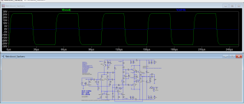
Yup, this might as well be a good project at the closing of the year 🙂. Harmonic profile and THD looks good at 7w power, square wave at 20Khz seemed pretty stable. I am hooked with Lineup's amp naming and so I will name this amp 'Retroboot'. It might also carry a retro logo/emblem..🤔😄
Attachments


Yes Sirs, it worked!..😃 and it sounds about right, well I am using a 3 way Panasonic micro-speakers (those thing may contain dividing network inside).
Just about as a newly built amp, dc offset needs further adjustment as I am reading 50mv. Bias current looks very good at +18mv on the positive side and -17.9mv on the negative side. It still needs more of playing hours to see if standing current is stable enough (does not jump while the amp is playing).
Anyone has any idea where to adjust so that I can come up with a lower dc offset? I only did an hfe measurement (analog mm) on both pairs of ltp input trannies hoping that they are 'matched in pair'. I could not make any further adjustment with LTSpice as the results seemed to be in optimal condition.
Thanks y'all!
Attachments


whoopps, I forgot to mention that I am using Sankens for the output, instead of the larger 2SC5200/SA1943.
I was fine tuning my circuit in MicroCap12 and I was surprised that MicroCap's Tian probe comes pretty handy. However comparing it with LTSpice, the results looks quite different. I used the same components on both program and I did not adjust any variables in MicroCap, I guess MicroCap reads it automatically (node where you placed the probe).
Any thoughts?
Any thoughts?
Attachments


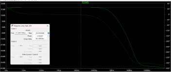
In the Bulgarian thread, it was stated that it uses 3 level frequency compensation (load and lag) to eliminate possible instability. It was unknown to me as I have not seen this phase shift leveling scheme before. I gave it a go because LTSpice says it will work, it worked and looks stable, sounds nice too!
I still wanted to work on it to drive 6ohms speakers because in sim driving 6ohms at 20khz harmonic distortion hits 2%. In the actual build I tested it to drive a 3ohms speaker it looks fine, I hadn't heard any distortion or seen any instabilities but that is only for a couple of songs play. I do not have my 'scope here in my current place so I could not actually verify it if it really was stable driving heavier loads.
I still wanted to work on it to drive 6ohms speakers because in sim driving 6ohms at 20khz harmonic distortion hits 2%. In the actual build I tested it to drive a 3ohms speaker it looks fine, I hadn't heard any distortion or seen any instabilities but that is only for a couple of songs play. I do not have my 'scope here in my current place so I could not actually verify it if it really was stable driving heavier loads.
Attachments


Last edited:
Did you mean the zobel network itself? I am also kind of confused here because MicroCap says it has plentiful of gain margin (23dB).BTW, you could remove RC from zobel network. It eats you gain margin at high frequency.
Remove the RC, and keep the coil.Did you mean the zobel network itself?
Phase shift leveling sounds like marketing language.t was unknown to me as I have not seen this phase shift leveling scheme before. I gave it a go because LTSpice says it will work, it worked and looks stable, sounds nice too!
If you can keep closed loop 10Hz to 100KHz flat, there will be no phase shift. Phase and magnitude are hand in hand. Any phase shift will exhibit also gain change.
Flat means less than 3dB difference.
Q9, upper NPN driver you mean? how to implement this...The bootstrap will saturate Q9 when clipping. Clamping diodes are needed.
Ed
I have placed D4 BAV21 in the VAS, will this also help?
Thanks!
Yes, the upper driver transistor will saturate. This amplifier will blow up when clipping at high frequencies. D4 does not help.
Place two diodes in front of Q9 (one from input to collector, another from input to base) to keep the base voltage from going above the collector voltage. A base-emitter resistor should also be added.
Ed
Place two diodes in front of Q9 (one from input to collector, another from input to base) to keep the base voltage from going above the collector voltage. A base-emitter resistor should also be added.
Ed
That’s for Q7, the VAS. Overload there isn’t always benign. Ed mentions Q9, the NPN driver - also subject to saturation at clipping. Yes it is, but any clamp diode will have more forward drop than the C-B junction (unless your supply is low enough to use a schottky) so it is of limited use. The typical overload in that position IS benign - unless you do stupid things like using TIP41 drivers.
If you want to eliminate it entirely, use a CCS instead of the bootstrap. Adding MORE diodes isn’t the answer as it negates the use of the bootstrap in the first place and one may as well use a CCS.
If you want to eliminate it entirely, use a CCS instead of the bootstrap. Adding MORE diodes isn’t the answer as it negates the use of the bootstrap in the first place and one may as well use a CCS.
- Home
- Amplifiers
- Solid State
- Unusual bootstrap standard EF