Hi,
I need a simple passive notch filter for 1 Khz..
I found this configuration with a calculator: http://www.learningaboutelectronics.com/Articles/Notch-filter-calculator.php#answer1
I built it as shown and all resistor and capacitor values are within 1 %.
When testing I see that the dip is around 1700 Hz. and not 1000 Hz..
So according to me something is wrong. Is there anyone with a second opinion?
Regards, Gerrit
Attachments

Output impedance of my GAG810 analog signal generator is 600 Ohm; input of my Kenwood AC voltmeter is 1 MOhm.
I understand this may influence the measurements, but it’s not part of the calculator, so I cannot calculate with this.
Regards, Gerrit
I understand this may influence the measurements, but it’s not part of the calculator, so I cannot calculate with this.
Regards, Gerrit
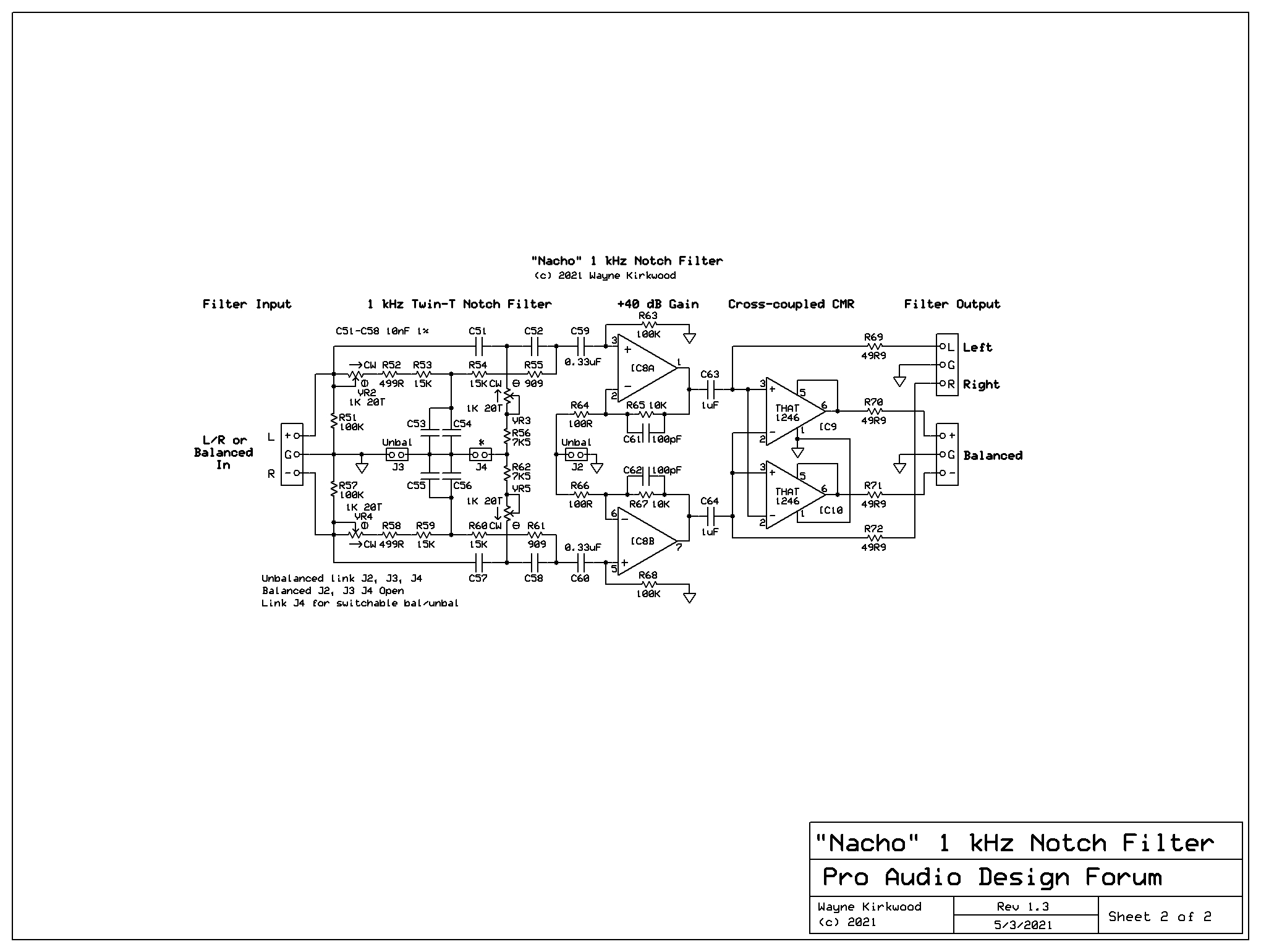
Use the notch filter values here: https://proaudiodesignforum.com/forum/php/viewtopic.php?t=1265
20 nF 15K9 and 10 nF 15K9/2.
20 nF 15K9 and 10 nF 15K9/2.
Doesn't matter Twin-T or Hall but usually nice to have the input buffer to use that notch with any source.
Hi Euro21,
I would like to try the Hall filter too. Could you upload the ltspice file too? I would like to test / verify a few things.
Thanks, Gerrit
I would like to try the Hall filter too. Could you upload the ltspice file too? I would like to test / verify a few things.
Thanks, Gerrit
Voilá.Hi Euro21,
I would like to try the Hall filter too. Could you upload the ltspice file too? I would like to test / verify a few things.
Thanks, Gerrit
Attachments

Hi,
I just tested the sim.okawa-denshi.jp filter. With the calculated components the actual, measured notch is at 1350 Hz.
I will do some more tweaking…
Regards, Gerrit
I just tested the sim.okawa-denshi.jp filter. With the calculated components the actual, measured notch is at 1350 Hz.
I will do some more tweaking…
Regards, Gerrit
Hi Edmond,
I will continue working towards a 1 kHz. notch by trial and error I guess. I had high hopes the calculators would give me the right figures.
Your DiAna software is downloaded and hopefully next week I will have some time to do some testing.
Regards, Gerrit
I will continue working towards a 1 kHz. notch by trial and error I guess. I had high hopes the calculators would give me the right figures.
Your DiAna software is downloaded and hopefully next week I will have some time to do some testing.
Regards, Gerrit
I concur with Sandy's revisions and I believe the values cited in the original post are incorrect. I do believe the formula in Sandy's sketch needs to be revised to
Notch Filter Frequency =1/(2 Pi RC).
Here's an intuitive way to think about the network. Recall that a series R and C network has a "corner frequency" of 1/(RC) radians/sec = 1/(2 Pi RC) Hz.
At the notch frequency, the Twin-T output amplitude is 0, so the output can be regarded as a virtual ground at notch center. With a virtual ground at the output, we can analyze each network arm independently. Consider the upper arm of the filter: the 2C capacitor sees source resistance R in parallel with R, or R/2. So the upper arm has a radian corner frequency of 1/(R/2 * 2C) = 1/(RC).
In like fashion, the R/2 resistor in the filter's lower arm sees C in parallel with C, or 2C. So the lower arm also has a radian corner frequency of 1/(R/2 * 2C) = 1/(RC).
I set up a quick twin-T to assess my soundcard distortion performance, but at the time used equal C's and R,R,R/4, with a trim on R/4. I used REW to measure and trim the notch frequency to 1kHz. The trimmed frequency noticeably drifted, which affected the notch depth. Low tempco parts may be your friend if you need a deep stable notch.
I then used a 1970's vintage boat-anchor distortion meter that included a professional analog twin-T that was tunable from 20Hz to 30kHz, and that gave negligible drift in frequency but some drift in notch depth (likely due to polyester foil caps).
I then used a 1970's vintage boat-anchor distortion meter that included a professional analog twin-T that was tunable from 20Hz to 30kHz, and that gave negligible drift in frequency but some drift in notch depth (likely due to polyester foil caps).
Thanks for uploading i was looking for this one but how to connect it with apmlifier? Before active tone controller or after?Hi,
I need a simple passive notch filter for 1 Khz..
I found this configuration with a calculator: http://www.learningaboutelectronics.com/Articles/Notch-filter-calculator.php#answer1
I built it as shown and all resistor and capacitor values are within 1 %.
When testing I see that the dip is around 1700 Hz. and not 1000 Hz..
So according to me something is wrong. Is there anyone with a second opinion?
Regards, Gerrit
The R and C values according the notch filter calculator ( http://www.learningaboutelectronics.com/Articles/Notch-filter-calculator.php#answer1), as well as the formula are correct. Not convinced? Have a look at the sim below.
Attachments


- Home
- Design & Build
- Equipment & Tools
- 1 kHz passive notch filter