Partiendo de una potencia de +-45 V, me gustaría armar un amplificador de 100 w con un solo par de 2SC5200 y 2SA 1943. ¿Me pueden recomendar un esquema fiable? Adjunto algunos esquemas que he encontrado de los cuales no tengo opiniones. Serían con solo un par de transistores de salida. Gracias.
Attachments
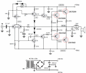
"Starting from a power of +-45 V, I would like to put together a 100 w amplifier with a single pair of 2SC5200 and 2SA 1943. Can you recommend a reliable scheme? I attach some schemes that I have found of which I have no opinions. They would be with only a couple of output transistors. Thank you."
1. A single pair of C5200/A1943 is asking for failure with a ±50V supply.
2. Tip41/42 are too slow for drivers.
3. Separate 100 Ohm resistors to turn off the outputs is too slow and asking for shoot-through current failure. They should be cross-coupled.
4. While VI protection can cause issues, you should at least have current limit protection.
5. A current mirror on the LTP is better for turn-on/off thumps as well as general performance.
6. Especially with a current mirror, the LTP needs to be degenerated to reduce slew distortion.
7. A Darlington VAS improves THD. See Douglas Self's web site.
8. The feedback decoupling cap should be voltage clamped.
...
Attachments
1. A single pair of C5200/A1943 is asking for failure with a ±50V supply.
2. Tip41/42 are too slow for drivers.
3. Separate 100 Ohm resistors to turn off the outputs is too slow and asking for shoot-through current failure. They should be cross-coupled.
4. While VI protection can cause issues, you should at least have current limit protection.
5. A current mirror on the LTP is better for turn-on/off thumps as well as general performance.
6. Especially with a current mirror, the LTP needs to be degenerated to reduce slew distortion.
7. A Darlington VAS improves THD. See Douglas Self's web site.
8. The feedback decoupling cap should be voltage clamped.
...

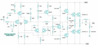
Would this design fit the characteristics you mentioned?"Starting from a power of +-45 V, I would like to put together a 100 w amplifier with a single pair of 2SC5200 and 2SA 1943. Can you recommend a reliable scheme? I attach some schemes that I have found of which I have no opinions. They would be with only a couple of output transistors. Thank you."
Attachments
1. A single pair of C5200/A1943 is asking for failure with a ±50V supply.
2. Tip41/42 are too slow for drivers.
3. Separate 100 Ohm resistors to turn off the outputs is too slow and asking for shoot-through current failure. They should be cross-coupled.
4. While VI protection can cause issues, you should at least have current limit protection.
5. A current mirror on the LTP is better for turn-on/off thumps as well as general performance.
6. Especially with a current mirror, the LTP needs to be degenerated to reduce slew distortion.
7. A Darlington VAS improves THD. See Douglas Self's web site.
8. The feedback decoupling cap should be voltage clamped.
...
Thank you
Attachments
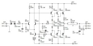
And likely few hundred more versions.Would this design fit the characteristics you mentioned?
Very common topology.
People would change few things here and there.
But for the most part would work.
Or a final design would be similar.
Has VI limiters
which many would leave out.
Depends on application.
Few strange values here and there.
Sure others will post more eventually.

- Home
- Amplifiers
- Solid State
- 100w amplifier with a single pair of 2SC5200 and 2SA1943