I had originally intended to just make a few small (EQ'd) sealed subwoofers; I like their sound-quality, size and simplicity. However I'd also like multiple (at least three) distributed ones for reasons of room-mode smoothing and room flexibility. In that case the subs may not be near the main speakers, so being able to 'localise' them would be unfortunate.
I'm convinced that most people can't localise sources below 80hz (certainly not below 60hz), especially if the sources are from multiple places simultaneously. But if the subwoofers output extraneous higher frequency noises (harmonics, resonances etc), then that could easily destroy the illusion. So I'm now considering 4th-order bandpass types of enclosure, because an acoustic low-pass filter will catch more sources/causes of higher frequencies than an upstream electronic filter. Though an acoustic band-pass is much more difficult to achieve, especially without degrading the audio quality itself. So this is all a bit tentative, and I shall reserve judgement on whether to go with bandpass or sealed for the final versions.
The drivers are like the venerable LAB12, which many people will be familiar with. My actual ones are from BK electronics here, named the FAB12; a small upgrade in specs but essentially interchangeable. They would have been ideal in small sealed boxes but I think they might also work in bandpass configurations. I'd forgotten how finnicky and buggy WinISD is (to be fair, it never got past beta, but I'm only just starting to find my way with Hornresp at the moment). However, with some persuasion WinISD has suggested this is possible:

A frequency response between 25hz and 80hz (-3db) up to 109dB at 1m (peaks) within Xmax - achieved from 320watts and 63L total internal volume. A 10cm diameter by 39cm long vent would reach about 27m/s air velocity, which is not ideal but (I gather) still within what many people seem to find acceptable for subs -assuming rounded vent ends.
There is a lot of talk around the internet of bandpass being slow and muddy, allegedly due to the vent output affecting timing in various ways. That is a concern, but the group-delay actually doesn't look too bad in winisd, at least. Here it is shown (for comparison) against a sealed box with typical high and low pass electronic filters instead of acoustic bandpass types; by comparison the bandpass is less smooth but I'm pleased to see that it isn't massively high at any point:

(the bandpass still needs a subsonic high-pass filter, according to winisd, hence one was added for the sim. Most sources/amps roll off by then anyway, but IMO better safe than sorry).
So i wonder if the poor reputation of the bandpass is due to also poor implementations. It is 'much' more affected by quite small deviations, which is no less of a concern to me, but one which could in theory be overcome. I guess the drivers would need to be well run in and the boxes tuned via actual measurements, rather than just applying generic driver specifications and winisd simulations.
Anyway, I had feared the bandpass box would need to be massive, but actually those sizes and SPLs seem reasonable. As I'm intending to go with distributed subs there will be at least three, so would total nearly 114dB at 1m, or 105dB at 3m/10' (before any remaining room modes muck things up). In practice I'd likely attenuate one or more of the subs for balancing, but also in practice some may be nearer than 3m/10'. So that still seems plenty for music (and occasional films) in quite modestly sized rooms, unless I'm being naïve.
So.... these were my initial thoughts and reasoning; if anyone spots flaws or disagrees I'd be very interested to know. This will be a slow project - time is limited and access to workshop facilities very rare. I'm also intending to pair these subs with another parallel and more complicated build; multiple entry horns. However, I have the drivers and so will hopefully be spending/wasting time on some kind of prototypes reasonably soon.
Cheers
Kev
I'm convinced that most people can't localise sources below 80hz (certainly not below 60hz), especially if the sources are from multiple places simultaneously. But if the subwoofers output extraneous higher frequency noises (harmonics, resonances etc), then that could easily destroy the illusion. So I'm now considering 4th-order bandpass types of enclosure, because an acoustic low-pass filter will catch more sources/causes of higher frequencies than an upstream electronic filter. Though an acoustic band-pass is much more difficult to achieve, especially without degrading the audio quality itself. So this is all a bit tentative, and I shall reserve judgement on whether to go with bandpass or sealed for the final versions.
The drivers are like the venerable LAB12, which many people will be familiar with. My actual ones are from BK electronics here, named the FAB12; a small upgrade in specs but essentially interchangeable. They would have been ideal in small sealed boxes but I think they might also work in bandpass configurations. I'd forgotten how finnicky and buggy WinISD is (to be fair, it never got past beta, but I'm only just starting to find my way with Hornresp at the moment). However, with some persuasion WinISD has suggested this is possible:
A frequency response between 25hz and 80hz (-3db) up to 109dB at 1m (peaks) within Xmax - achieved from 320watts and 63L total internal volume. A 10cm diameter by 39cm long vent would reach about 27m/s air velocity, which is not ideal but (I gather) still within what many people seem to find acceptable for subs -assuming rounded vent ends.
There is a lot of talk around the internet of bandpass being slow and muddy, allegedly due to the vent output affecting timing in various ways. That is a concern, but the group-delay actually doesn't look too bad in winisd, at least. Here it is shown (for comparison) against a sealed box with typical high and low pass electronic filters instead of acoustic bandpass types; by comparison the bandpass is less smooth but I'm pleased to see that it isn't massively high at any point:
(the bandpass still needs a subsonic high-pass filter, according to winisd, hence one was added for the sim. Most sources/amps roll off by then anyway, but IMO better safe than sorry).
So i wonder if the poor reputation of the bandpass is due to also poor implementations. It is 'much' more affected by quite small deviations, which is no less of a concern to me, but one which could in theory be overcome. I guess the drivers would need to be well run in and the boxes tuned via actual measurements, rather than just applying generic driver specifications and winisd simulations.
Anyway, I had feared the bandpass box would need to be massive, but actually those sizes and SPLs seem reasonable. As I'm intending to go with distributed subs there will be at least three, so would total nearly 114dB at 1m, or 105dB at 3m/10' (before any remaining room modes muck things up). In practice I'd likely attenuate one or more of the subs for balancing, but also in practice some may be nearer than 3m/10'. So that still seems plenty for music (and occasional films) in quite modestly sized rooms, unless I'm being naïve.
So.... these were my initial thoughts and reasoning; if anyone spots flaws or disagrees I'd be very interested to know. This will be a slow project - time is limited and access to workshop facilities very rare. I'm also intending to pair these subs with another parallel and more complicated build; multiple entry horns. However, I have the drivers and so will hopefully be spending/wasting time on some kind of prototypes reasonably soon.
Cheers
Kev
Last edited:
It would be possible, but your sim is not showing the port resonances and upper stuff that will still come out the vent.However, with some persuasion WinISD has suggested this is possible:
Hornresp will give a better idea, but still does not account for upper breakup modes.
I have designed and built bass reflex (BR), tapped horns (TH) front loaded horns (FLH) and a bandpass (BP) box for LAB 12s.So I'm now considering 4th-order bandpass types of enclosure, because an acoustic low-pass filter will catch more sources/causes of higher frequencies than an upstream electronic filter.
The BP box, called the "Bowtie" had a similar response to yours, though shifted up about 1/3 octave, and a +3dB "bump" between 40-50Hz:
The small rear chamber keeps excursion under control even below the BP tuning.
A LP filter alone is enough to remove the upper "gack":
The LAB subs are pretty clean until run past Xmax.
Objectively, measured distortion levels were not much different between the Bowtie and the bass reflex cabinet.
Subjectively, though both BR & BP had similar low frequency response (the BR also had a +3dB "bump" between 40-50Hz) and were both EQed to the same response, the BP did not have the articulation of the BR, bass lines seemed more ambiguous, kick lacked "punch" by comparison.
In a word, the BP sounded "rubbery".
But the BP could fit in the trunk of my car, and survive rentals.
Didn't withstand FedEx shipment though:
Tipping cabinets off the back of a truck is not advisable
")
As a testament to the LAB12 suspension, it supported the weight of the magnet structure and frame without tearing..
Cheers,
Art
Last edited:
Thank you, Art, as always, for your valuable thoughts. I'm envious of your opposing pairs; that would be close to my ideal, it is a shame that money and space are so restrictive for my little home projects. It is a bit shocking to see the broken driver, I had a real LAB12 in the past and it is much the same as my current FAB12s ; they are pretty well made so it must have taken a real thump to do that to the poor thing! I suppose a pressed steel basket wouldn't have shattered like a cast one, but it might have distorted.
Yes, I realised that the acoustic front filter is imperfect and also introduces some noise of its own. For my situation, it already makes the extra difficulty and size of a BP seem less worthwhile. But the (huge) nail in the coffin here is your perception of the LAB12 BP sounding "rubbery"; that is not something I want to invite in this situation, since I don't have the SPL & size requirements to justify the trade off. I can get sufficient, albeit sadly a little less, SPL and low end for my needs with a sealed or reflex box.
So that is very valuable to hear. I could have spent weeks, likely months, discovering for myself what you already know.
Thanks again,
Kev
Well in light of the above, I will probably go back to a closed/sealed enclosure. The following simulation suggests there is about 5dB difference between bandpass and sealed at Xmax (shown here with an 18hz high-pass filter to reduce undue room excitation). 5db is very significant at these low frequencies, but I think tolerable for my modest living room situation given that all port/vent issues no longer exist.

Another mitigating bonus is that the sealed one is smaller; in fact the one shown here is even half the volume.
Were I rich enough, or were equivalent SPL needed, then the sealed drivers could be doubled-up (and used in dual-opposing configuration for less vibration) in the same cabinet volume as the single bandpass, and reach slightly more SPL before xmax. Albeit at double the amplifier power and twice the driver cost.

It is tempting but I'll probably stay with one driver and save the driver & amp cost and the extra volume. These lowest 2 octaves are already costing more than all the higher frequencies combined.
Another mitigating bonus is that the sealed one is smaller; in fact the one shown here is even half the volume.
Were I rich enough, or were equivalent SPL needed, then the sealed drivers could be doubled-up (and used in dual-opposing configuration for less vibration) in the same cabinet volume as the single bandpass, and reach slightly more SPL before xmax. Albeit at double the amplifier power and twice the driver cost.
It is tempting but I'll probably stay with one driver and save the driver & amp cost and the extra volume. These lowest 2 octaves are already costing more than all the higher frequencies combined.
Last edited:
EQed to the same response, I'd prefer the sealed for sound quality over the BR if the SPL is adequate.5db is very significant at these low frequencies, but I think tolerable for my modest living room situation given that all port/vent issues no longer exist.
That said, the BR would be idling at half the excursion of the smaller sealed box for nearly the same SPL, half (or 1/4..) the amplifier power and half the driver cost.
I wouldn't consider vibration a sound quality issue in a well braced, heavy cabinet.Were I rich enough, or were equivalent SPL needed, then the sealed drivers could be doubled-up (and used in dual-opposing configuration for less vibration) in the same cabinet volume as the bandpass, and reach slightly more SPL before xmax.
Side mounted dual opposed drivers can be a problem in a corner- one driver becomes "slot loaded", a cavity resonance issue.
Art
On balance, I could be happy with a direct radiator for both sound quality and SPL in my small room. My main interest in bandpass was the acoustic low pass filter, rather than an increase in SPL. But the acoustic filter is not perfect or without disadvantages, so overall I'm coming to think that the extra size and complexity is not entirely warranted for my needs.
Though exposing the driver does absolutely require that it won't make much extraneous higher frequency noise. I shall only really find that out when the first one (or prototype) is built. But I don't remember the LAB12 (that I had previously) making noticeable noise and my FAB12s look to be of similar build quality, so I have reasonably high hopes.
Yes, that does still leave the decision between Bass Reflex and Sealed. The extra efficiency of BR is very attractive in a number of ways, but in my domestic setting it is perhaps mostly about economics; I would always prefer sealed 'if' I can justify the cost for amp power and quantity of drivers. We shall see; thankfully though, both are relatively safe options if the drivers are well behaved, so neither would be an awful choice.
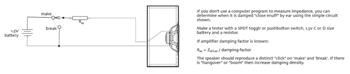
That graphic shows shorting the battery, not a good idea.FWIW/YMMV, etc., I used BP6 corner subs to mate to 110 Hz FLH @ 120 Hz above them and found that tuning to a rising response and critically damping them to 'taste' was the 'hot ticket' for me.
In the switch "Make" position, the driver resistance completes the circuit, in the "Break" the circuit is open, no short circuit in either position.That graphic shows shorting the battery, not a good idea.
It is easy to read that way; if the switch's 'hinge' had been the left dot rather than the right, it would have shorted. Anyway, I have used the click test in the past and it can work well, though I'm happy that one can measure with computers these days. So I'll want to get my laptop running again by that point, certainly if I make anything more complex or unforgiving than a sealed box.
Which I still may... GM clearly got on okay with bandpasses and I've also had very favourable reports from another member, who suggested trying it for myself before deciding. Which I agree would be a more complete approach, given that experiences seem to differ. So I probably will, if I can find the time; it would just cost for some materials, since I have the drivers already. Something cheap like chipboard flooring would likely suffice for testing purposes.
Which I still may... GM clearly got on okay with bandpasses and I've also had very favourable reports from another member, who suggested trying it for myself before deciding. Which I agree would be a more complete approach, given that experiences seem to differ. So I probably will, if I can find the time; it would just cost for some materials, since I have the drivers already. Something cheap like chipboard flooring would likely suffice for testing purposes.
A slight delay as I moved on from winisd to learn how to use hornresp for bandpass simulations. It can handle more bandpass types and the modeling is a lot more detailed. That detail has been quite helpful in understanding some of the trade-offs related to the port, which winisd can't include.
What I've been able to glean is that whilst long ports allow the desired frequency response with smaller enclosures, they can also resonate (significantly) at frequencies above the passband. This defeats the whole objective for me, since the aim of using bandpass designs was specifically for their acoustic filter to block such spurious frequencies, not contribute to them. It is an acoustic resonance, so I'm expecting that any electrical low-pass filtering will be fairly ineffective at reducing the resonances, and (as I understand it) this is the air-mass resonating, not the port walls/materials itself, so physical damping of the tube won't help much either. And I want to keep port velocities low, to avoid them making additional out-of-band chuffing noises, so the ports cannot just be made shorter and therefore narrower (unless SPL is reduced).
So that means shorter ports and bigger boxes would be the way for me to go, here. Pretty big unfortunately, for a small living room. They can be made a bit smaller if one allows peak(s) in the frequency response (to be attenuated by EQ/DSP) but are still fairly large. Given this, and the fact that the acoustic filter is not going to be perfect anyway, I'm starting to think that bandpass designs won't work well for me - due mainly to space requirements. Which is a shame, as on paper they look very good otherwise. But, apparently, real life imperfections mean that resonances aren't always as crisp/sharp/loud as hornresp calculates, so I'll probably still build a test box or two to see what actually happens.
Hi Kev,
There's some talk here about port resonances on BP systems. I never got round to building a test box to test to destruction but the sub that I posted measurements from in the thread was used for years on my TV system without any noticeable resonance problems.
Rob.
There's some talk here about port resonances on BP systems. I never got round to building a test box to test to destruction but the sub that I posted measurements from in the thread was used for years on my TV system without any noticeable resonance problems.
Rob.
An electrical low-pass filter drops the SPL of the pipe resonances as can be seen in the "Bowtie " band pass sub in post #2.What I've been able to glean is that whilst long ports allow the desired frequency response with smaller enclosures, they can also resonate (significantly) at frequencies above the passband. This defeats the whole objective for me, since the aim of using bandpass designs was specifically for their acoustic filter to block such spurious frequencies, not contribute to them. It is an acoustic resonance, so I'm expecting that any electrical low-pass filtering will be fairly ineffective at reducing the resonances, and (as I understand it) this is the air-mass resonating, not the port walls/materials itself, so physical damping of the tube won't help much either.
Though the BP6 acoustic band pass should attenuate upper harmonics, the driver's excursion is greatest at the low and top end of the band pass, least in the center.
The Bowtie (using LAB12) generated far higher levels of upper harmonic distortion than in any of the other cabinets I had used it in, probably due to the much higher excursion in the 80-125Hz range.
Art
Thank you, both. Interesting stuff; I clearly need to test what happens in practice, then, since it isn't quite as I imagined, or as I simulated, in a number of ways.
One thing which may help is that I'm hoping the upper rolloff will be about 80hz, as this is for hifi rather than PA type applications. But I don't need much below 30hz either, since film/movies are less important to me than music. Though this will rely on my MEHs reaching that low, and they're not only unproven but also not built yet. So we shall have to see.
One thing which may help is that I'm hoping the upper rolloff will be about 80hz, as this is for hifi rather than PA type applications. But I don't need much below 30hz either, since film/movies are less important to me than music. Though this will rely on my MEHs reaching that low, and they're not only unproven but also not built yet. So we shall have to see.
A little more exploration. If the ports are as long as I'd like for smallest boxes, they do resonate at too low a frequency and so too close to the desired pass band. But there might (well) be a viable middle ground; if the boxes are a bit bigger then the ports can be shortened enough to resonate at one or maybe two octaves above the upper roll-off frequency, especially if this is kept low (more like 80hz than 120hz). 0.5m would be fair, 1m might be tolerable - at that point the first resonances are roughly 340hz to 170hz; the former at least seems sufficiently clear of the desired signal to leave it largely unaffected were the amp to be low-passed.
I still need to look at excursion and the upper harmonic distortion that Art mentioned. In my simulations the greatest excursion appears around 20-30hz though, so I'm hoping that perhaps harmonics will be somewhat more attenuated by the time they reach higher, localisable frequencies.
I still need to look at excursion and the upper harmonic distortion that Art mentioned. In my simulations the greatest excursion appears around 20-30hz though, so I'm hoping that perhaps harmonics will be somewhat more attenuated by the time they reach higher, localisable frequencies.
Last edited:
Just to put a few numbers on this for my future reference as much as anything else. This is where I started (4th order bandpass) with a nice in-band frequency response from a total (both chambers) of about 60L. But.. a port nearly two feet long and a very big port resonance below 300hz:

Increasing to a total of about 80L allows a shorter port. Pushing the resonance higher and significantly attenuating it:

Some DSP would now be needed to flatten the in-band response. So there would be no gain in SPL for the extra chamber volumes
Taking that a step further to a total of 105L allows a port less than half as long as my original, and so pushes the resonance even higher:

(the extra junk just above that is just due to chamber reflections/resonances that I was also investigating).
To show that (of course) Art is right about electrical filtering being of aid, I added a crude electrical low-pass filter:

The grey line is unfiltered, the red is with a 4th order low-pass; considerably better. By having pushed the resonance higher (than my initial design), the low-pass filter has minimal detrimental effect on the desired frequency response. No doubt a better result could be achieved with better more targeted DSP, and probably also cope with the resonance being lower and closer to the pass-band; so with DSP huge acoustic measures would be less necessary.
So.. it is looking feasible to use 4th order bandpass, but better results are obtained from boxes that are getting quite a lot bigger than I wanted, especially as the aim is for a number of distributed ones. By comparison here is a simple sealed box of only 40L:

That is less than half the cabinet volume of any of the above BP4s (it could be made even smaller with a bigger amplifier), and of course there are no port resonances to cause problems. Though it loses 5dB at 30hz (relative to the bandpass design) which can't be mitigated with EQ due to Xmax being reached.
So I could manage a BP4 after all, but the extra size means the benefits of the acoustic filter (and/or any other sound qualities) would need to be significantly audible to justify the extra size and weight. The extra 5dB is nice, but not the main deciding factor for my application. I'm still looking at BP6 but so far the minimum size seems even larger. Unfortunately though I lost (overwrote) my most promising hornresp simulation. I seem to do that fairly often as a beginner with the application; my usual way of working misses having a 'save as' button.
Increasing to a total of about 80L allows a shorter port. Pushing the resonance higher and significantly attenuating it:
Some DSP would now be needed to flatten the in-band response. So there would be no gain in SPL for the extra chamber volumes
Taking that a step further to a total of 105L allows a port less than half as long as my original, and so pushes the resonance even higher:
(the extra junk just above that is just due to chamber reflections/resonances that I was also investigating).
To show that (of course) Art is right about electrical filtering being of aid, I added a crude electrical low-pass filter:
The grey line is unfiltered, the red is with a 4th order low-pass; considerably better. By having pushed the resonance higher (than my initial design), the low-pass filter has minimal detrimental effect on the desired frequency response. No doubt a better result could be achieved with better more targeted DSP, and probably also cope with the resonance being lower and closer to the pass-band; so with DSP huge acoustic measures would be less necessary.
So.. it is looking feasible to use 4th order bandpass, but better results are obtained from boxes that are getting quite a lot bigger than I wanted, especially as the aim is for a number of distributed ones. By comparison here is a simple sealed box of only 40L:
That is less than half the cabinet volume of any of the above BP4s (it could be made even smaller with a bigger amplifier), and of course there are no port resonances to cause problems. Though it loses 5dB at 30hz (relative to the bandpass design) which can't be mitigated with EQ due to Xmax being reached.
So I could manage a BP4 after all, but the extra size means the benefits of the acoustic filter (and/or any other sound qualities) would need to be significantly audible to justify the extra size and weight. The extra 5dB is nice, but not the main deciding factor for my application. I'm still looking at BP6 but so far the minimum size seems even larger. Unfortunately though I lost (overwrote) my most promising hornresp simulation. I seem to do that fairly often as a beginner with the application; my usual way of working misses having a 'save as' button.
Last edited:
So possibly the smallest BP4 I can manage is around 60L with a 46cm port and electronic low-pass filtering to reduce the out-of-band port resonance. Something like this but with an extra notch filter at the port resonance:

The difference between the nicer red curve and the grey is that the latter has 'lossy Le' enabled and power reduced (necessary, as excursion increases). I presume that the grey curve is unfortunately likely to be the more accurate. But it isn't a big deal as I'd be using EQ/DSP to truncate the peak anyway - probably at around 110dB, for flatness from 30hz to ~90hz. Port velocity peaks at about 20m/s around 40hz, though that too will reduce a bit as things are EQd. Perhaps with flared ends, I could allow a higher velocity than that, and so reduce the port size and so shorten it.
The sim does seem to be getting quite sensitive to small alignment changes and a bit peaky - I wonder if sizes this small are pushing things too much, and so likely to adversely affect sound quality. For all I know, it might be that a bandpass could sound great if given the space, but rubbish if squeezed too much. Or it might be better, by controlling excursion more closely. But either way I think this is about my size limit so if I'm going to test one it might as well be this or thereabouts.
The final option that I've come up with is based on more extensive DSP: allowing me to make the front/ported chamber tiny. This allows a larger rear chamber for the same total size, so a more pleasing low-end roll-off. It also pushes the top-end roll off higher than needed - hence the greater need for DSP correction. However, the bonus of the latter is that much more aggressive low-pass or notch filters can be used to curb port resonances, as now we actually want/need to increase the rate (or reduce the frequency) of the upper roll-off over what is acoustically provided.
For a rough example, a 45L rear chamber and 10L front/ported chamber. Even with a crude 4th order low-pass (signal) filter very close to my intended upper roll off frequency, there is more than enough output left to need further attenuation.

For a rough example, a 45L rear chamber and 10L front/ported chamber. Even with a crude 4th order low-pass (signal) filter very close to my intended upper roll off frequency, there is more than enough output left to need further attenuation.
Kev,
Your BP sims have ranged from 105L to 55L, with 30Hz output ~110dB, presumably excursion limited.
For comparison, in this undersized 64.4L BR sim with an Fb of 29Hz, excursion at 30Hz is only ~5mm, output ~114dB, about "twice as loud" as your BP sims, +9dB over sealed.
It reaches the FAB12's Xmax of 16mm at 43Hz ~117dB.

The pipe resonance peak won't be as large as the sim shows.
Port velocity is under 25m/sec, about the same as the Hornresp estimates my 36Fb LAB 2x12, I never noticed any port noise with it when driven to or a bit past Xmax.

I could tell at a distance when Xmax was exceeded by more than 4mm, the grill cloth (removed in the photo above) would flap
At any rate, the upper transient response of a direct radiator compared to the delayed reaction of a BP port won't be conveyed in any sim.
Art
Your BP sims have ranged from 105L to 55L, with 30Hz output ~110dB, presumably excursion limited.
For comparison, in this undersized 64.4L BR sim with an Fb of 29Hz, excursion at 30Hz is only ~5mm, output ~114dB, about "twice as loud" as your BP sims, +9dB over sealed.
It reaches the FAB12's Xmax of 16mm at 43Hz ~117dB.
The pipe resonance peak won't be as large as the sim shows.
Port velocity is under 25m/sec, about the same as the Hornresp estimates my 36Fb LAB 2x12, I never noticed any port noise with it when driven to or a bit past Xmax.
I could tell at a distance when Xmax was exceeded by more than 4mm, the grill cloth (removed in the photo above) would flap
At any rate, the upper transient response of a direct radiator compared to the delayed reaction of a BP port won't be conveyed in any sim.
Art
- Home
- Loudspeakers
- Subwoofers
- 12" bandpass Subwoofers