Ok, the last file you sent runs instantly. As before, I don't see any changes to the settings. What did you do?
Also, and pardon my ignorance; why are we using an AC sine source – or rather, seeing as it's rectified and smoothed; why can one not measure DC voltages with aforementioned rectified and smoothed source?
Is it because a SPICE generated DC source will be perfect and have no ripple? That shouldn't prevent DC measurements from being taken.
Of course I am very glad that you've shown me the sine source option, and I did notice in the setup that you put the second one 180 deg out of phase 🙂 So obvious when you think about it but maybe not so much when just getting started.
We used an AC source for two main reasons.
1/ It shows dynamically how good (or bad) the circuit is for producing clean DC. We can see exactly how much ripple there is. We could also be smart and rig up a switched load varying between two values and look at the regulation of the supply.
You could also reduce the value of the main reservoir caps and look at how that affects the final ripple voltage.
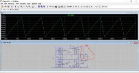
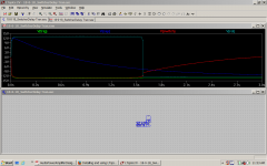
2/ We can also see if the regulator is stable under all conditions. Look at the images. This shows the +18 volt rail when the 3300uF cap is reduced in value. So we have a problem. The basic design is unstable and is relying on loads of capacitance to force it to be stable which isn't good. The second image is a close up of that noise and oscillation.
Sometimes simulation files don't run (or don't converge as its called) and the original could have been such an example. It doesn't actually happen all that often. The OP34 type opamps seemed to be an issue though and possibly not suitable in real life as well as simulation. When there is a lot of random detail to plot (random instability at a microvolt level) then things probably just appear to stall. That would be my best guess.
A DC voltage source is perfect in every way and can supply billions upon billions of amps with not a uV drop 😀 There is an option to add series resistance to the supply and sometimes adding say 0.1 ohm makes it more realistic. Of course there is still no ripple.
If you don't want to set up a bridge (or diode) and reservoir cap then we can still simulate a fixed level of ripple. Take a look at image 3. That generates a waveform approximating 50Hz ripple. The peak is at 45 volts and the trough at 40 volts. In the last image I changed that to 28 and 25 volts.
1/ It shows dynamically how good (or bad) the circuit is for producing clean DC. We can see exactly how much ripple there is. We could also be smart and rig up a switched load varying between two values and look at the regulation of the supply.
You could also reduce the value of the main reservoir caps and look at how that affects the final ripple voltage.
2/ We can also see if the regulator is stable under all conditions. Look at the images. This shows the +18 volt rail when the 3300uF cap is reduced in value. So we have a problem. The basic design is unstable and is relying on loads of capacitance to force it to be stable which isn't good. The second image is a close up of that noise and oscillation.
Sometimes simulation files don't run (or don't converge as its called) and the original could have been such an example. It doesn't actually happen all that often. The OP34 type opamps seemed to be an issue though and possibly not suitable in real life as well as simulation. When there is a lot of random detail to plot (random instability at a microvolt level) then things probably just appear to stall. That would be my best guess.
A DC voltage source is perfect in every way and can supply billions upon billions of amps with not a uV drop 😀 There is an option to add series resistance to the supply and sometimes adding say 0.1 ohm makes it more realistic. Of course there is still no ripple.
If you don't want to set up a bridge (or diode) and reservoir cap then we can still simulate a fixed level of ripple. Take a look at image 3. That generates a waveform approximating 50Hz ripple. The peak is at 45 volts and the trough at 40 volts. In the last image I changed that to 28 and 25 volts.
Attachments


Hi Mooly,
A lot of what you've just explained I experienced for myself last night while experimenting with a simple timing circuit, using your sine psu.
When a simulation produced the attached image, a light suddenly went on, figuratively speaking. I think part of the problem for me that inhibits learning (I'm an Aspie) is I need a kind of 'overview' of whatever it is that's being studied. What is blatantly obvious to others is often shrouded in mystery to me. At school, I always did better learning from a 'worked' example. When working on a new model, say a complex AVR, I find it helpful to take a few minutes to study the block diagram which helps me understand how all the many different sections function together.
Having used this program for less than a week, I'm still very much in 'a state of wonder', trying to comprehend the vastness of this incredible resource.
When the attached image was produced, I only then realised that the simulation can be run repeatedly, without reapply all the probes again. Also, that it seems I can attach as many probes as I like and get to see this beautifully choreographed dance of electrical signal function in the circuit. At that point I also understood the necessity of clearly labelling all the points of interest 🙂
So, a picture is indeed worth a thousand words. At a glance I see the trigger event (in this case an interruption in the V+ supply to part of the op-amp based circuit) initiate a capacitor discharge sequence, which at a certain threshold causes a relay to latch (a transistor takes one side of the coil to ground). I also tagged a transistor switch just out of curiosity. All the action takes place just after the 1.5s mark and with the initial setting of 1 in the tran setup page, was being missed entirely. Changing the timing cap value and the time setting resolved all that. For a beginner like me, Slow is the operative word 🙂
The voltage scale is a bit weird because I used your split rail supply. The circuit I was examining didn't need that. Being a bit lazy, I used the outer +&- rails and then I had ripple galore. Even a cap between V+&- did nothing. I had to add one between each supply rail and the centre tap and that got rid of it.
As always, your helpful comment and attached images are much appreciated. I will study them today.
Attachments
I've only scratched the surface of what LT can do tbh but I agree that it is a fabulous design tool.
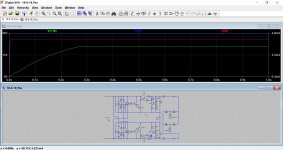
I don't know if you have tried this but as well as just looking at voltages you can also look at currents all on the same screen. Just hover over a resistor or cap and click. The current will be displayed with a new scale at the right of the screen.
This shows the 18 volt rail again, and also the current in R2 and R4.
I can't make your last circuit out 😀 At any time you can place the cursor on the circuit diagram workspace/screen and just hit the spacebar. The circuit will resize back to fill the window. The scroll wheel should allow you to some in and out and you can also drag the circuit around.
Attachments
Just browsed a batch of service manuals, Aiwa to Zoom.
For anyone who is interested;
All primary windings of transformers in power supplies are on the left of the page.
Power flows from left to right as does signal. Maybe your schematic is a mirror image?
Not that it matters, just a sanity issue for me and anyone else in the trade that has been reading service manuals for over 50 years.
I've only scratched the surface of what LT can do tbh but I agree that it is a fabulous design tool.
I don't know if you have tried this but as well as just looking at voltages you can also look at currents all on the same screen. Just hover over a resistor or cap and click. The current will be displayed with a new scale at the right of the screen.
This shows the 18 volt rail again, and also the current in R2 and R4.
I'm just learning ltspice too, and love it, its a wonderful tool.
One thing I did in the little circuit I was modeling was to add some 0.01 ohm resistors in places where I wanted to see the current.
Randy
I must say, when I first looked at the diagram I was rather surprised at the method of regulation myself. What made it worse was it's a commercial design and it wasn't regulating very well at all.
This is probably offtopic, but could you please expand a bit? What do you find unusual? Why do you think it is not regulating well?
Apart from the slight weirdness of the reference voltage i cannot see anything strange. In fact i am curious about the product, as very few commercial units show this kind of effort. Can you reveal what this is?
[FONT=AvantGarde Bk BT, sans-serif]Off topic? Not at all 🙂
That psu is configured to output 18-0-18v. I was getting 15-0-17v. Not what you'd expect from a psu with that many parts 🙂 It seemed to be affected by temperature too; the hotter the set got, the greater the error.
[/FONT] [FONT=AvantGarde Bk BT, sans-serif]
The first thing I did was to see if there was enough 'headroom' for the regulators to function. Many manufacturers don't take the world's widely varying mains supplies properly into account. As it turns out, there was more than enough.[/FONT] [FONT=AvantGarde Bk BT, sans-serif]
Looking at the top half, the psu max output current is limited by R3, which also makes it inherently short circuit proof. Simulating it in SPICE made me realise this value was likely cut a bit fine for the expected current draw. Of course, if something were to go wrong with the load, that would account for it too. With regard to R3, you actually do want to 'cut it fine' as there is a heat penalty if you are too generous with the max current you allow. It was absolutely fascinating to see in SPICE the heat dissipation effects on the various key transistors, both pass and shunt elements, when altering R3 and simulating different loads. [/FONT] [FONT=AvantGarde Bk BT, sans-serif]
As you've asked; what I found unusual is that they derive the desired output voltage by shunting surplus current (after the pass element) to ground, not by controlling the pass element as I would have expected. So I guess I was surprised because it seemed 'illogical' although it seems to work well in SPICE. Mooly would be a better person to ask about how widespread this design practice actually is, and the pro's and con's of it.[/FONT]
[FONT=AvantGarde Bk BT, sans-serif]With regard to where it comes from....although I haven't been expressly forbidden from sharing the source, I haven't exactly been given the go-ahead either, so I would prefer to clarify that with the manufactures first. Sorry, hope you understand, and thanks for your input 🙂[/FONT]
Thank you for the detailed response!
This is quite a standard shunt regulator. Very popular in more ambitious diy projects and really high-end commercial audio. The only voltage headroom required is sufficient voltage drop across Q5 so it can convincingly act as a current source. 5v is usually enough, 10v is better. The constant current is determined by (Vled-0.7)/R3.
In this particular case the current seems to be around 380mA. This current is shared between the load and the shunt Q3. No way of saying if the design is bad without knowing the expected current draw of the load. Normally it should not exceed 300-330mA as sufficient current has to pass through Q3 for best performance.
I'm just learning ltspice too, and love it, its a wonderful tool.
One thing I did in the little circuit I was modeling was to add some 0.01 ohm resistors in places where I wanted to see the current.
Randy
The beauty of LTSpice is that it isn't fazed by big or small numbers. If you want to measure current then a 0.0000001 ohm resistor would have almost zero influence and yet still allow current to be measured.
Don't forget you can read current directly on transistor leads and the leads of the voltage sources. You just need a bit of accurate mouse control to get the cursor on the correct position (at which point the cursor symbol changes to show you have it correct).
Nice, I didn't realize that, but just tried it and figured out I needed to put the cursor at the corner of the part to get emitter or collector currents.
That's it 
You can use that method on pretty much any component lead such as opamp pins, caps, coils...
You can use that method on pretty much any component lead such as opamp pins, caps, coils...
Nice, I didn't realize that, but just tried it and figured out I needed to put the cursor at the corner of the part to get emitter or collector currents.
Me too 🙂 That's why I was inserting those resistors! Thanks for confirming.
Just browsed a batch of service manuals, Aiwa to Zoom.
For anyone who is interested;
All primary windings of transformers in power supplies are on the left of the page.
Power flows from left to right as does signal. Maybe your schematic is a mirror image?
Not that it matters, just a sanity issue for me and anyone else in the trade that has been reading service manuals for over 50 years.
All? Really? 🙂 🙂
I closed my eyes and just chose one at random. Good choice it was too. It's an older one scanned from a good old fashioned paper service manual.
Attachments

Thank you for the detailed response!
This is quite a standard shunt regulator. Very popular in more ambitious diy projects and really high-end commercial audio. The only voltage headroom required is sufficient voltage drop across Q5 so it can convincingly act as a current source. 5v is usually enough, 10v is better. The constant current is determined by (Vled-0.7)/R3.
In this particular case the current seems to be around 380mA. This current is shared between the load and the shunt Q3. No way of saying if the design is bad without knowing the expected current draw of the load. Normally it should not exceed 300-330mA as sufficient current has to pass through Q3 for best performance.
You're welcome 🙂
[FONT=AvantGarde Bk BT, sans-serif][FONT=AvantGarde Bk BT, sans-serif]That's very interesting, that this topology is favoured by the folk you mention. Do they give any particular reasons for choosing such a design over some of the more advanced (and much easier to implement) TO220 styled regulators? If you do happen across a really good example, I'd love to see it.[/FONT][/FONT]
...realised that the simulation can be run repeatedly, without reapply all the probes again. Also, that it seems I can attach as many probes as I like ... necessity of clearly labelling all the points of interest 🙂
Yes the sim can be re-run.
And (at least in Pspice) "all" internal voltages are recorded, but only the ones with probes are shown. I can add probes to the schematic, without re-sim, to see what happened on the nodes I didn't know I needed to know about.
Yes, rational labeling quickly becomes essential to sanity.
Not too inclined to cry about a 3 minute sim. Today it is often a second, but I remember Early Days when a 1-transistor circuit would take 20 minutes to run. I rigged command-line SPICE with a beep program so I could go off and do something else.
Last edited:
Yes the sim can be re-run.
And (at least in Pspice) "all" internal voltages are recorded, but only the ones with probes are shown. I can add probes to the schematic, without re-sim, to see what happened on the nodes I didn't know I needed to know about.
Yes, rational labeling quickly becomes essential to sanity.
Not too inclined to cry about a 3 minute sim. Today it is often a second, but I remember Early Days when a 1-transistor circuit would take 20 minutes to run. I rigged command-line SPICE with a beep program so I could go off and do something else.
Thanks for that, yes, LT also records everything. Very convenient with Long-Play sims 🙂 I was playing with a sim today where I modeled my relays using the datasheet coil resistance paralleled with the usual 4148 for the back emf. It ran in 2 secs. Then I thought I'd be clever and add the coil inductance in series with the resistance. Fortunately the datasheet gives all that. That same sim ran in slow motion. I've seen snails in my garden go much faster 🙂 I am aware of the voltage controlled switch by the way and have used one elsewhere in a circuit where I wanted to simulate a mechanical rotary switch.
For utterly illogical (and therefore all too human) reasons, we are quite unable to agree which side of the road to drive on, or what voltage to use for our household electricity service.All? Really?
The fact that these ridiculous disagreements cost our species a great deal of unnecessary money, and even worse, a vast number of unnecessary deaths every year, makes no difference. We still can't bring ourselves to agree.
So it's quite unlikely we'll ever all agree on the best conventions to use when drawing a schematic. We're human, we don't do the logical thing when the wildly irrational is a perfectly good alternative. 🙂
That said, the convention I grew up with was: signal flow from left to right, DC voltage from bottom to top. This applies whether you're drawing up a moving-coil preamp, a power supply, or an FM radio. Most of those books I learned electronics from as a child came from the local British Council Library, so it's quite likely they were following a British (or possibly European) set of conventions.
Since then, particularly in North America, I have certainly seen plenty of published schematics that abused those conventions, most particularly in the automotive world, where non-standard symbols are frequently used even for something as basic as an SPST switch.
Nevertheless, particularly for analogue circuitry, I think those conventions are a good way to make a schematic more readable and understandable and intuitive.
LTSpice is a fantastic way to study an existing circuit, and to the software, it makes no difference if you draw the circuit upside down, inside out, or backwards.
But to invent a new electronic circuit, you still need to develop the ability to put components together in your mind's eye, until they do what you want them to do. And that mental ability is much more achievable when every circuit you study over a period of many years, always follows the same convention. (Imagine how much harder it would be to get good at tennis if you held the racket upside down on Tuesdays and Thursdays, behind your back on Mondays and Wednesdays, and between your toes on Fridays and weekends?)
Just the night before last, I woke up from a deep sleep at about 2 AM with a fully formed circuit idea in my head. I pulled out the notepad, pen, and flashlight I keep by the bed in case of exactly such middle-of-the-night inspirations, and quickly drew the schematic (signal flow left to right, DC voltages bottom to top, of course).
The next day I simulated it in LTSpice, and it worked immediately. A couple of small tweaks in LTSpice, and now the simulation works a little better than my 2 A.M. idea did. Next step, to build a prototype and see what reality says.
Would I have woken up with a working circuit diagram in my head at 2 AM if I hadn't learned electronics from schematics that always followed the left-to-right, bottom-to-top convention? No way to prove it either way, but I suspect the answer is, probably not.
I suppose I should be thankful that North American pianos don't have the highest treble notes on the left and the lowest bass notes on the right, and that British written music notation doesn't put the treble at the bottom of the staff and the bass at the top! 😀
-Gnobuddy
For utterly illogical (and therefore all too human) reasons, we are quite unable to agree...
...the convention I grew up with was: signal flow from left to right, DC voltage from bottom to top.
...in North America,... particularly in the automotive world, where non-standard symbols are frequently used even for something as basic as an SPST switch.
Imagine how much harder it would be to get good at tennis if you held the racket upside down on Tuesdays and Thursdays, behind your back on Mondays and Wednesdays, and between your toes on Fridays and weekends?)
"DC voltage from bottom to top": plus up or plus down?
Vacuum tubes tend to be minus and common down.
Older telephone relays suffered less electrolysis if common was positive.
The earliest commercial transistors were PNP and naturally + common.
Older relay diagrams did not run power buses but tended to show a battery and ground at each place power was needed; the electricians understood there was about one battery for the whole system and they ran wires to it.
Modern "ladder logic" relay-tree is drawn Line on one side, Neutral the other, circuits run horizontal, and relay contacts may be nowhere near their coils.
A big book on relays that I just got is very plain: the many-many different fields that USE relays all developed individual styles and often the style follows directly from function in that field. Also relays have both electrical and mechanical connections and it is often useful to break both for drawing clarity.
Between when we revolted and WWII, the US and GB developed different styles for mechanical drawings; so different that when Rolls-Royce plans were brought to America so Packard could make fighter engines, they re-drew the top-front-side layout to US conventions so there would be no costly screw-ups in our factories.
Broskie has said that Power Supply Right-to-Left is good to his eye; with great respect for Broskie's other thoughts and excellent amplifier drawings, this one leaves me cold.
More Broskie Snazzy Schematics
In algebraic order for signed real numbers: most negative voltage at the bottom, most positive at the top."DC voltage from bottom to top": plus up or plus down?
And this perfectly fits the convention, usually putting the B+ rail near the top edge of the schematic.Vacuum tubes tend to be minus and common down.
I like this particular convention a lot, as it lets me visualize electric potentials in a circuit as height above sea level, so to speak, zero volts being sea level. You can then "see" which way currents will flow in a schematic - always downhill through resistors, always uphill through power supplies and batteries (unless you wire two power supplies back-to-back and one beats out the other, in which case, current through the weaker power supply flows downhill.)
Electrons, of course, go the opposite way to the current flow. That's just algebra, and has nothing to do with electrons as such; it applies equally to bank transfers of negative amounts of money.
From what I've seen, this particular schematic-drawing convention (most negative voltage on the bottom) seems to have been frequently violated during the short era when PNP germanium transistors were the hot new thing (and the only type of transistors that were widely available.)
But once NPN silicon devices took over, the "most negative on the bottom" convention seems to have come back into wide use. PNP transistors were now usually drawn "upside down", with the emitter on top and the collector on the bottom.
Like RPN (Reverse Polish Notation) calculators, ladder logic seems to be entirely its own thing, and very confusing to those who grew up with other types of electronics. I've seen a couple of those ladder logic diagrams, and more or less fled the scene crying for my mommy.Modern "ladder logic" relay-tree is drawn Line on one side, Neutral the other, circuits run horizontal, and relay contacts may be nowhere near their coils.
-Gnobuddy
- Status
- Not open for further replies.
- Home
- Amplifiers
- Power Supplies
- 18-0-18 PSU - First attempt at using LTspice