Hi all,
First time posting here so apologies if I incorrectly post or don't follow standard posting procedure.
I was recommended to post here for advice on a repair I'm working on for a volunteer society.
Bit of background, I'm an electronics engineer by trade so feel free to load technical information on me.
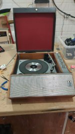
A customer at our volunteer repair society brought in this lovely 1960s transistor vinyl player, with an issue with the sound.
It will play perfectly fine at low volume, not incredible audio quality but manageable. The bass and treble dials adjust the sound accordingly so no issue there.
The issue is that when you raise the volume to be loud enough to listen to at a distance, the output of the speakers seems to saturate and can't generate the full sound.
I've tested the speaker directly with another amplifier and there's no issue there in terms of volume.
My suspicion is that the transistors (AD162 and AD161 in AB configuration) have failed after ~60 years of life.
It's been repaired once before, but I believe they swapped out an electrolytic, diode rectifier and a BJT due to the condition of those on the board and the ugly solder joints they left.
The issue comes to replacing them, as germanium transistors are somewhat pricey to get, and my understanding is that the best way to get a good sound is to make sure the gains for the complementary transistors are more or less equal.
The solution I have reasoned and also found online is to buy ~5 of each NPN and PNP and find the best combination of pairing to find some vintage transistors with a similar gain.
The issue with this is that it's quite expensive to buy a bunch of germaniums! The other solution would be to maybe retrofit the board to use silicons, and change out the bias diode accordingly but I feel like that's a big undertaking.
I've attached a bunch of pictures of the device and the best shot at the schematic that I could find which confirmed my suspicion of looking at the board that it's an AB class amplifier.
Any input on the problem/solution would be much appreciated!
First time posting here so apologies if I incorrectly post or don't follow standard posting procedure.
I was recommended to post here for advice on a repair I'm working on for a volunteer society.
Bit of background, I'm an electronics engineer by trade so feel free to load technical information on me.
A customer at our volunteer repair society brought in this lovely 1960s transistor vinyl player, with an issue with the sound.
It will play perfectly fine at low volume, not incredible audio quality but manageable. The bass and treble dials adjust the sound accordingly so no issue there.
The issue is that when you raise the volume to be loud enough to listen to at a distance, the output of the speakers seems to saturate and can't generate the full sound.
I've tested the speaker directly with another amplifier and there's no issue there in terms of volume.
My suspicion is that the transistors (AD162 and AD161 in AB configuration) have failed after ~60 years of life.
It's been repaired once before, but I believe they swapped out an electrolytic, diode rectifier and a BJT due to the condition of those on the board and the ugly solder joints they left.
The issue comes to replacing them, as germanium transistors are somewhat pricey to get, and my understanding is that the best way to get a good sound is to make sure the gains for the complementary transistors are more or less equal.
The solution I have reasoned and also found online is to buy ~5 of each NPN and PNP and find the best combination of pairing to find some vintage transistors with a similar gain.
The issue with this is that it's quite expensive to buy a bunch of germaniums! The other solution would be to maybe retrofit the board to use silicons, and change out the bias diode accordingly but I feel like that's a big undertaking.
I've attached a bunch of pictures of the device and the best shot at the schematic that I could find which confirmed my suspicion of looking at the board that it's an AB class amplifier.
Any input on the problem/solution would be much appreciated!
Attachments


Resistor values may have drifted, usually increased, and the working point of some transistor may not be correct anymore. The idle current trimmers, if present, may also need a cleaning. I would start by measuring the power supply voltage, then check the value of the resistors. Electrolytic capacitors look very old, they also need to be checked after replacing the faulty resistor.

This looks quite suitable as a near drop-in, and has high gain, just use one channel. Or maybe there's a mono version.
Use the existing supply, with proper polarity connection.
https://www.amazon.com/dp/B07XBKTNKF/ref=sspa_dk_detail_2
Use the existing supply, with proper polarity connection.
https://www.amazon.com/dp/B07XBKTNKF/ref=sspa_dk_detail_2
It's fully transistorized!Hi all,
First time posting here so apologies if I incorrectly post or don't follow standard posting procedure.
I was recommended to post here for advice on a repair I'm working on for a volunteer society.
Bit of background, I'm an electronics engineer by trade so feel free to load technical information on me.
A customer at our volunteer repair society brought in this lovely 1960s transistor vinyl player, with an issue with the sound.
It will play perfectly fine at low volume, not incredible audio quality but manageable. The bass and treble dials adjust the sound accordingly so no issue there.
The issue is that when you raise the volume to be loud enough to listen to at a distance, the output of the speakers seems to saturate and can't generate the full sound.
I've tested the speaker directly with another amplifier and there's no issue there in terms of volume.
My suspicion is that the transistors (AD162 and AD161 in AB configuration) have failed after ~60 years of life.
It's been repaired once before, but I believe they swapped out an electrolytic, diode rectifier and a BJT due to the condition of those on the board and the ugly solder joints they left.
The issue comes to replacing them, as germanium transistors are somewhat pricey to get, and my understanding is that the best way to get a good sound is to make sure the gains for the complementary transistors are more or less equal.
The solution I have reasoned and also found online is to buy ~5 of each NPN and PNP and find the best combination of pairing to find some vintage transistors with a similar gain.
The issue with this is that it's quite expensive to buy a bunch of germaniums! The other solution would be to maybe retrofit the board to use silicons, and change out the bias diode accordingly but I feel like that's a big undertaking.
I've attached a bunch of pictures of the device and the best shot at the schematic that I could find which confirmed my suspicion of looking at the board that it's an AB class amplifier.
Any input on the problem/solution would be much appreciated!

Thanks all for the replies, sorry for the slow response - I only get a chance to have a stab at this at the weekends.
I removed from the board and checked all of electrolytics with a LRC and they're all (incredibly) still performing and within +-10%.
DC voltage after the rectifier is a solid 25V with no ripple, so supply voltage is fine.
As for the schematic, the only one I could find is that tiny thumbnail which obviously I couldn't read any values from, just the broad layout.
The resistor Pcan mentioned measures 1ohm, but with the paint having come off, I don't know what the real value is.
On the datasheet for the AD161 there's a suggested schematic for audio amplifier which seems to match pretty closely (apart from bias diode) to the vinyl board...
-- Some time later after getting nowhere --
I ended up finding a site that had the schematic and shelling out 2 euros for the schematic so I could properly diagnose it. The resistor Pcan mentioned is supposed to be a 1ohm so that wasn't the issue. The paint must have just been knocked off at some point as they were all a little bit flakey.
Turns out one of the transistors had failed and I had something on hand that was suitable to replace it with! Which was rather fortunate.
I've included a snippet of the datasheet as I didn't want to give away a source of income from the place I got it from (https://www.service-data.com/) as they made my life a lot easier having the full schematic.
Transistor TR2 is a BC213L, so nice and generic to replace - I used a 2N3906 in the end and works like a charm.
R20 was the resistor Pcan spotted, and is a 1ohm pair with R21 between the two Germaniums TR4 and TR5.
I now get a nice sound out of the player, and I just need to give it a good clean and install it back in.
Thanks for the input all!
Attachments

- Home
- Amplifiers
- Chip Amps
- 1960s Transistor Vinyl Player Repair - Ultra 6018B