You risk getting off spec factory rejects to outright fakes at those prices.
And your volumes will not interest any factory representative to give you a price break.
And consider the landed cost at your doorstep, in order to compare the price.
It is going to cost something for the item to be packed and sent to you, count that in your per piece cost.
If you want to save $5 and spoil your project it is your decision.
Diodes Inc 4.6 cents apiece qty 1000 from Mouser. I’ll spend $46 once and never have to worry about 1N4007’s again. 21 cents each plus shipping every time you need a handful just doesn’t make any sense. Those off brand ammo packs cost me a whopping $9 each. Are they real? Probably. Absolutely sure? No. They conduct in one direction, and the Vf drops about 2mV per C. They’ve found their way into a lot of low power supplies and bias circuits and haven’t had one misbehave yet. It saves the 4007’s in stock for times when I need to count on it blocking 1000 volts. Sometimes a diode is a diode is a diode.
I can't say anything about a kit. I just think there has not to be too large capacitance. I have different caps at hand so I would rather use 2.2..10 nF caps.So if the kit came with 100nF C1/2/4/5 replace them with 2.2nF or 4.7nF before soldering the kit?
A typical snubber for your circuit is something like a 10-22 R resistor and 0.47-1.0 uF ceramic cap. I use film caps only with high voltages, >= 50..100 V.What would be typical R & C values for a snubber suitable for a 250 mA DAC supply built with LM317/LM337 and 1A rated transformer?
My experience of rectifiers is for low volts just use 1n400x with no snubbers or caps across them.
For higher volts I found I could get away with just Schotkies. HER158G is good.
Certainly sorted out a noisy valve pre amp running off 150VDC.
For higher volts I found I could get away with just Schotkies. HER158G is good.
Certainly sorted out a noisy valve pre amp running off 150VDC.
Naresh -
You can't hear 150 kHz, but your circuits can... They can behave weirdly in response to out-of-band stimulus.
You can't hear 150 kHz, but your circuits can... They can behave weirdly in response to out-of-band stimulus.
A typical snubber for your circuit is something like a 10-22 R resistor and 0.47-1.0 uF ceramic cap. I use film caps only with high voltages, >= 50..100 V.
Is it ok for me to solder them across the transformer terminals/lugs? Or is it better to keep it close to the bridge rectifier on the PCB?
It is ideal to put it right across a transformer secondary but usually we use PCB for mounting parts, so we put it on the PCB.Is it ok for me to solder them across the transformer terminals/lugs? Or is it better to keep it close to the bridge rectifier on the PCB?
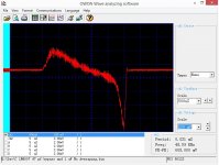
Here are some actual measurements.. Hover over the thumbnail for the title. Snubbers can reduce the bounce, but better rectifiers don't cause one.
Attachments
-
 1N4007 24VC 600 Ohms 470 Uf No Scope Average.jpg139.3 KB · Views: 153
 -
 47 pF per diode and 1 uf Transformer snubber 1N4007 24VC 600 Ohms 470 Uf No Scope Average.jpg133.7 KB · Views: 144
 -
 47 pF per diode snubber 1N4007 24VC 600 Ohms 470 Uf No Scope Average.jpg135 KB · Views: 140
 -
 Basic setup 24 VAC 600 Ohm 470 uF With Silicon Carbide Rectifiers.jpg132.8 KB · Views: 135
Last edited:
I measured 48 different rectifiers in 2015 and published the results in Linear Audio volume 10.
Linear Audio's publisher, Jan Didden (an active member of diyAudio!) sells either the whole volume, or individual articles as pdf downloads. Here's a link.
Linear Audio's publisher, Jan Didden (an active member of diyAudio!) sells either the whole volume, or individual articles as pdf downloads. Here's a link.
simon7000, perhaps those plots would mean something if you also link to a test circuit schematic that shows operating conditions, and identify what circuit voltage difference was probed, and what the probe was and the acquisition instrument, and include a photo of the test environment.
24Vac winding - what is the transformer VA and the winding resistances ?
Is the rectifier a full bridge?
Is the 470uF the capacitor input filter?
Is the 600 ohm the DC loading across the filter?
The above info is needed to do a basic PSUD2 simulation to identify what the diode current waveform is likely to be.
Where is the probe connected in the circuit?
What is the scope bandwidth with the probe used?
Do you have a photo of the test setup, to indicate why there may be noise in the plot?
What was the SiC part?
Is the method mentioned in this thread?
Good enough 1N4007: https://datasheet.lcsc.com/lcsc/1810181810_Changzhou-Starsea-Elec-1N4007_C84641.pdf
Personally, I use HER108 instead.
Personally, I use HER108 instead.
Aren’t HER10x gone now? I used up the last of mine more than 10 years ago, and was having trouble locating more. Sort of replaced by UF400x.
Octopart.com finds many thousands of HER108 on the shelf and ready to deliver. It's an extremely handy resource.
- Home
- Design & Build
- Parts
- 1N4007 Rectifiers: Does Brand Matter?