For your info and possible interest,
An "old" prototype design. Look at the Evatco Project Pages here:
Evatco Hammond Project Page
and scroll down to the KT88 120W Ultralinear.
Schematics and some designer notes there. I actually built and tested one monoblock. It worked very well and sounded good. It uses a Hammond 1650T Output Transformer. I actually also tried a Plitron PAT4006 Toroidal Output Tranny in this prototype and decided that I liked the Hammond.
The schematic shows unequal zobels from anode to screen on the push and pull sides. They should actually be set the same.
This is a project I always intended to return to - just did'nt get around to it, mostly because I don't need 120Watts per channel. The prototype monoblock is still intact and sitting on a shelf in the workshop.
Cheers,
Ian
Hi All,
I'm interested in building a dual channel tube amp that can produce up to 500 w rms per channel.
But I'm not finding any schematics for my little beast. Does any one know where I might start to make the concept a reality using parts available in today's world.
thanks
You could buy a low power valve amp then mic it up to a solid state amp.
Or even use the output from a small valve amp attenuated into a solid state amp.
Gingertube: put EH KT90 in lieu and 500V B+ and one just scrapes 150W. Drop to 450V, (permits use of single 500V psu caps) and one gets 100W. IMO the EH KT90 is an excellent tube, with a lower sat volt way better than the KT88; With high snubber C values on the screen -anode; don't be tempted to force a 10K signal through the amp at Hi power: the Zobel R will stew. Unequal component values signify unequal capacitances within the primary.
richy
richy
Richy,
Will keep that in mind. Once I can clear the decks of existing (mine and others) projects I want to get back to it. I mainly posted that for people to use as a starting point.
I have on the shelf waiting:
2 x Hammond 1650T (2000 Raa to 4,8,16 Ohms)
2 x Custom Power Trannies I had wound locally to suit
2 x PAT4006 Plitron Output Trannies (2000 Raa to 6 Ohm, 40% UL Taps, 100W)
2 x VDV2100-CFB/H Output Trannies (2000 Raa to 6 Ohm, 10% CFB + 30% UL taps, 100W)
6 x Plitron Matching Toroidal Power Trannies
2 x Plitron 10H matching Torroidal Power Chokes
10 matched Gold Lion re-issue KT88
10 matched EH 300B
The pair of PAT4006 Outputs, the 10H Chokes and 2 off the Plitron Power Trannies are intended for Parallel Push Pull (PPP) 300B monoblocks (about 35W Class A or 60W Class AB)
The pair of VDV2100-CFB/H and 2 off the Plitron Power Trannies are intended for PPP KT88 with UL and Cathode Feedback (about 100W per channel) - note that the 10% Cathode feedback working with the 30% UL Taps gives effectively 40% UL Operation.
The 2 Hammond 1650T will probably go to Guitar Amps - I want to try 8 off 6V6 in PPP just because every 6V6 Guitar Amp I've done (either 1 pair or 2 pairs to date) have sounded lovely.
So I can't make the excuse that I can't start the next project because I can't afford the parts. Parts are sitting on the shelf waiting for me to get off my butt.
Other peoples projects to complete.
I cleared a JCM900 Marshall this week (blown output tranny, fitted a Hammond replacement).
I have a 90W SS HiFi Amp to finish this and maybe next week (approx 1V offset in one channel + bad hum).
I have a genuine 1963 VOX AC30 waiting to restore. This guy at least is more interested in having a top class job than having finished "immediately".
Cheers,
Ian
Alot of you will be hard pushed to get this result form other sim parallel p-p o/p transformers; in pic. performance of the Sowter 8659 2.2KA-A ;150W lump ,20Hz-75Khz f3dB: custom speck'd. The Zobel in my case arrives mathematically at 2n2 1K5 for each half and the result is shown in pic. It isn't that critical. The important data is knowing the self resonance freq and this can be empirically found..
Hint; one can crib the same Zobel analysis for switchmode BEFORE 1st stage phase compensation and global nfb step cap are fitted. One does one before the other and one is lost.
The same waveform is obtained throughout the KT90-KT88-6550 group. THD dependant on circuit but I get around 0.1% at 150W 1Khz using the Williamson slam diff driver technique.
richy
Attachments

For your info and possible interest,
An "old" prototype design. Look at the Evatco Project Pages here:
Evatco Hammond Project Page
and scroll down to the KT88 120W Ultralinear.
Schematics and some designer notes there.
Interesting design, the parts labeling on the schematic is a bit confusing however, it there a parts listing other than the schematic that I could reference.
examples
R7
4R7
Radd3
SOT
R13
3M3
Toddbailey,
This is a fairly standard "engineering" way of specifying stuff
Radd1, Radd2 etc identify the fact that there is no provision on the PCB for these parts and they are to be "tacked on".
4R7 means 4.7 Ohms. On a printout the "." will often go missing so we write "4R7" rather than 4.7. Similarly 3M3 means 3.3 MOhm.
AND "SOT" means "Select ON Test".
Hope this helps.
Cheers,
Ian
Figured I would throw my two cents in here. I've read many diy audio forums but have never posted so here goes! I am currently building a 500 watt per channel stereo amplifier. It is intended for bass guitar amplification. My design is based on a 400 watt bass amplifier I successfully built last year. This monster is quite above and beyond that project so I'll let you know what you're up against.
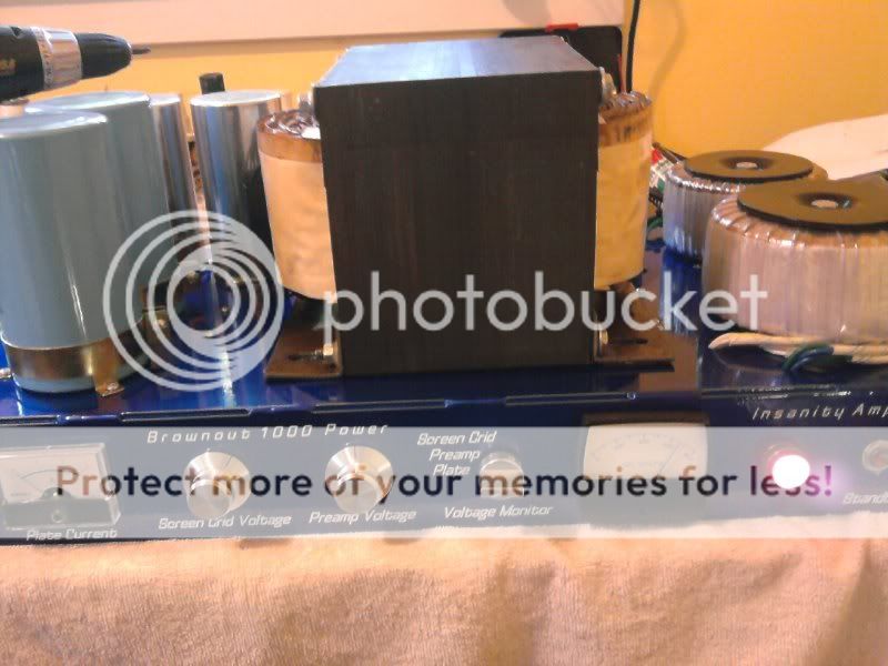

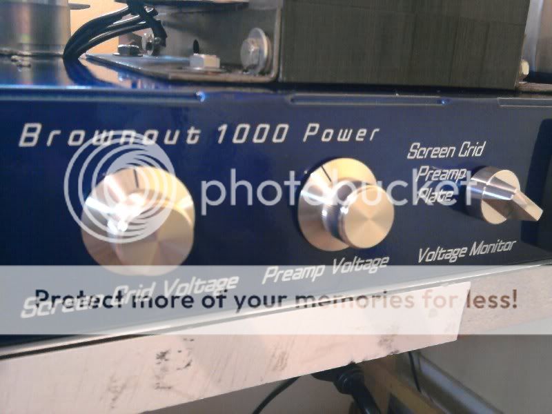
First off, this amplifier is too large and heavy to fit on one chassis or in one cabinet so I opted to build the power supply on one chassis and the amplifier on a second chassis. Each custom chassis is 24"x12"x3", 1/8" thick aluminum, powder coated and silkscreened. This amplifier will have 20 kt88s and 6 12ax7 preamp tubes(2 channel switching preamp), and mosfet follower drivers for the output tubes. I just finished building the power supply and it weighs 115lbs! Here's a few pictures to prove it!
The plate transformer is a 3kw, 440V industrial control transformer wired in reverse. With no load the power supply is putting out about 650vdc which I expect to drop to around 600V with the amp is powered up. I have nothing I can load test it with so I will just have to wait until the amp is complete. I was able to get this transformer used on ebay for $75. It alone ways 75lbs and I would rather have a toroid but the cost of a custom transformer would be far too expensive. The preamp and screen grids for the output tubes have separate, adjustable regulated supplies with a range of ~280V to 420V and run off a separate 300w antek toroidal transformer along with another 300w toroidal transformer that supplies the output tube heaters, regulated preamp heater supply, regulated 12V and 5V supplies for cooling fans and digital logic that controls the preamp. There are also regulated 24V and -120V supplies for the mosfets and bias circuitry. Those monster caps on the top of the chassis are 4700uF each, wired in series, and are paralleled with 2 series wired 80uF motor start caps to take care of any high frequency hash from the rectifiers. This power supply required me to design my own circuit board for all the regulated supplies and soft start circuit for the plate transformer and screen grid/preamp transformer. I still have yet to design the pcbs for the preamp and power amps.
I've spent about $1500 on the power supply and expect to spend at least $3000 more on the amp which is mostly for output transformers and tubes. I plan on using 2 paralleled plitron 300 watt toroidal output transformers per channel or having custom toroids manufactured by trafomatic. They built custom power and output toroids for my 400 watt bass amplifier and that amp rocks! There will also be a switch that bridges the amp for a single 1000 watt mono output. I'm not sure if a 15A breaker will even be able to handle this beast at full power. It will definitely have to be running on a dedicated circuit. I've been working on this baby for about 7 months and expect it to take at least another year to compile all the parts I need, design, and build everything. And of course fixing all the problems that arise with a project of this magnitude. Hope this helps!
I have nothing I can load test it with so I will just have to wait until the amp is complete.
Light bulbs! I use ordinary house light bulbs for testing big power supplies. I am in a 110 volt country so 5 100 watt bulbs in series will stress test a 500 volt power supply. The start up current of a light bulb is huge, so you either need a variac, or suitable surge limiting designed into the power supply (preferable or even mandantory at this power level).
Light bulbs! I use ordinary house light bulbs for testing big power supplies.
Or heater elements (from ovens or bathroom heaters). I have 4 on hand from an oven that was trashed, hundreds of watts per element, approximately 50R per element and I can combine them in various ways to get the resistance I need.
One more cheap source of dummy loads is hand held hair dryers. They are cheap enough you can afford to buy a new one and take it apart, And they come with nice built-in AC powered cooling fan. But recently I just bought a couple of those large size ceramic tube power resistors with an adjustable tap.
I hate to say it but waiting until the entire amp is done and then using the amp to test the power supply is a bad idea. Build the supply FIRST, then test it for a good long time under load and several power cycles. Measure the ripple voltage and check if anything gets hot under load after an hour or so.
Next wire the output transformer and power tubes and bias and check that you at least get clicks out a connected speaker.
The idea is to build and test one section at a time. The key is the testing. Build out only as much as you need to support the next test. The last step is to connect the stages together
I'd recommend running the amp full load for 6Hrs to get a proper idea of transformer temp rise. I found 6 hrs was necessary when testing the transformer in the Firefly amp.
You need to have the B+ fully loaded as well as having all the filament windings fully loaded to properly test it.
You need to have the B+ fully loaded as well as having all the filament windings fully loaded to properly test it.
Build the supply FIRST
I have always done things in life backwards, but I build the power supply last. Maybe this isn't a big deal on a "normal" amplifier, but if you are going into uncharted teritory why restrict yourself to the voltage that your power supply has.
When building a tube amplifier on a limited budget the choice of OPT is often limited. This item will determine the maximum power that your amp can put out. Once that is determined, the tube and circuit choices can be made. Then one or more prototypes can be built and tested. The prototype can be optimized for best power, distortion, efficiency and tube life. One of the important knobs to turn during optimization is B+ voltage. Once the prototyping is done then you will know the exact power supply requirements.
Of course having several lab type power supplies helps a lot. Careful shopping netted all of them cheaply though.
Yes I understand the need to test each section individually before testing the entire amp as a whole. This is the normal process I use for any new design. The only problem with this one is the size of the power supply and the amount of power it takes to run it fully. I never thought of using light bulbs or heater elements. Good suggestions although it would take quite a few to load it all the way. 20 kt88's running 100 watts a pair at 560V will draw approximately 3A which is 1,680 watts and I would probably want to go beyond that and test it to say 2000. That would be 20 100 watt light bulbs! I'm not too concerned with my transformers being able to handle the job. Its the screen grid supply and the heat sinking for the regulator that I am most concerned about. It must deliver 300V, 300mA. This I can easily test with a large 1k power resistor which I have not done yet.. but will! As for the heat - I really need to be load testing all the supplies simultaneously to get an idea for the total temperature rise. The aluminum chassis is one giant heat sink that is going to spread heat from all the transformers and regulators around.
which is 1,680 watts and I would probably want to go beyond that and test it to say 2000.......I'm not sure if a 15A breaker will even be able to handle this beast at full power.
I don't know where you are in the world, but here in South Florida USA a wall outlet can give you 1800 watts (15 amps at 120 volts) and the total draw on that circuit is 2400 watts (20 amps 120 volts). If you decide to use this amp on the road (where else would you need 1.21 gigawatts of power) power can be iffy and limited.
You need 201 watts to light up 20 X KT88 and 23 watts to light 6 12AX7's. That's 225 watts that gets turned into heat, not output power. Now you have about 1600 watts for making sound. Assuming pentode mode you will need about 20 mA per screen grid. Thats 400 mA, assuming 300 volts on the screen, there goes another 120 watts. I have measured a plate efficiency on a pair of KT88's at 75 watts in the 65% range. To get 1 KW total output power you will need about 1540 watts of plate input power at 65% plate efficiency. Add 'em up, thats 1885 watts input and 885 watts of heat. This assumes a 100% efficient power supply, which doesn't exist. You will need a strong wall outlet, and a cold climate or a good air conditioner.
The heat factor (it's hot here all year round) and the fact that I have tripped the breaker several times already during experiments control how big my amp will be. These two factors limit my amp to the 250 - 400 WPC range depending on the total efficiency and heat loss. This means limiting the number of tubes and using sweep tubes for higher efficiency. Methods for deactivating pairs of tubes for normal listening will be implemented.
I got a pair of "400 watt at 20 Hz" Plitron OPT's from their surplus page a few years back. I have already cranked 500 watts through them without issue. Plitron sells a similar 400 watt OPT still, but it is not cheap. A bass guitar (assuming standard tuning) goes down to 40 Hz, so a 400 watt OPT rated for 20 Hz can handle more than 400 watts at 40 Hz, a lot more.
I'm in Portland, Oregon and we have the same 15 amp service that you do. I realize I will not be able to use the full 1000 watts in my residence. Maybe various venues I play have higher capability, we shall find out! I really doubt I'm going to need to crank this one up all the way though. I will probably be using only half the power most of the time. It will be a stereo amp with the ability to turn either half on standby. Right now I'm using a 400 watt, 8 kt88 amp that I built, running into a speaker enclosure with 8 10" speakers. It is a very powerful amp and is plenty enough to keep up with two guitar players with 100 watt heads and 4x12 cabinets. They are considering upgrading to full stacks though so I will be outgunned! Not with this amp and another 8x10 cabinet though... I play a six string bass and the low B has a fundamental of 31 Hz so low frequency response is absolutely necessary. That's why I like the plitron transformers. They are designed for bass guitar amplification and that is what I intend to use.
The official derating for residential electrical equipment with continuous load is 80%, i.e. the 15 amp outlet, breaker and associated 14 ga. copper wire is rated by NFPA to carry 12 amps of continuous load (1440W at 120V) when installed with all the proper clearances etc. A 20 amp circuit can carry 1920W.
From personal experience this is not a particularly conservative limit for branch circuits. Noticeable heating occurs with the common AC hardware that plugs into these circuits (IEC connectors, 16Ga cords...) at around 8 amps continuous load.
Fortunately, your amp playing music will likely never need to deliver more than about 10 to 50 watts of continuous power to the speakers unless you use it as a radio station modulator or to power a stadium PA.
For my high power amp project I have secured 20 amp AC hardware with the large blade IEC style connector and a 14 gauge power cord. I'm expecting about 1200W total AC draw for 600W audio out, and will only need this when testing the amp. Idle draw will "only" be about 300W, and playing music not much more.
Cheers,
Michael
Yeah there's no way I will ever be pumping 1000 watts continuously into my speakers. All that power is mostly to have a huge amount of headroom and of course the wow factor. I'm using a neutrik powercon ac power connector which is rated at 20 amps and also a 14 gauge power cable.
A little late to the party but an old clothes dryer heating element makes a great load bank for diy projects. They can be found at the curb on trash day for free. And I like free.
The last one I tested was about 6 ohms.
BTW has anyone ever used a microwave transformer for a tube amp. Or just the iron and rewound. They also are free on trash day.
Tad
The last one I tested was about 6 ohms.
BTW has anyone ever used a microwave transformer for a tube amp. Or just the iron and rewound. They also are free on trash day.
Tad
- Status
- Not open for further replies.
- Home
- Live Sound
- Instruments and Amps
- 200- 500 watt Tube Amp project