Well you have definitely made a change.
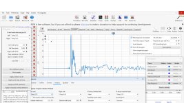
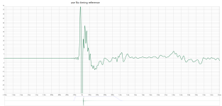
If you now look at the bottom of the window the window has "flipped" around in post 28 the tail of the window is on the left hand side, and now on the latest it is on the right hand side.
I think if you can keep it in that mode and bring the tail in, i.e. moving it to the left to 200u and -1.8m and observe what it does in terms of your frequency response as you move from right to left you are removing more of the room measurement ideally just need to be in front of the first reflection. Although I am not sure which is the real reflection. Others will add to this I am sure.
Thank you for support Juhazi, but i can´t change the mesaurements impulse even if i press shift and try to drag it to 0/Zero.Ref time can be moved in REW by pointing with mouse, then pressing Shift and dragging. Reference goes to highest amplitude (peak) automatically and when left window is long (as by default)
It still minus and only the "pin Ref" will follow the mouse.
Or i maby do something wrong?
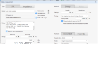
I have REW versin V5.31.1, and i don´t get the same "settings-pics" as you show in your post.
Like this it looks for me.
Regards John
Attachments
Today im going to make some new mesaurements, and i now understand why i have minus/- value at "Ref time"
Nice people before give the advice to " gate" the mesaurement to 3-8 ms.
And i diden´t know where in REW settings i should do that setting, but thought it was in the "window" that shows when you click "Measure"
There you have the alternative ( under Timing) to use "Aucustic timing reference", and when you chose it also set the "ms".
So i thought that was a "gated" measure.......But i was obvious doing settings in the wrong place!
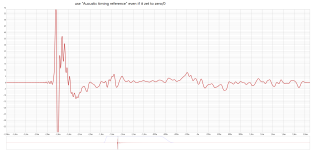
And i notice REW always get minus/- impulse-readings when you "click" use "Aucustic timing reference" even if it zet to zero/0
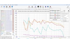
Test 2 new measurement, one with use "Aucustic timing reference" zet to zero/0.
And one using "no timing reference"
Nice people before give the advice to " gate" the mesaurement to 3-8 ms.
And i diden´t know where in REW settings i should do that setting, but thought it was in the "window" that shows when you click "Measure"
There you have the alternative ( under Timing) to use "Aucustic timing reference", and when you chose it also set the "ms".
So i thought that was a "gated" measure.......But i was obvious doing settings in the wrong place!
And i notice REW always get minus/- impulse-readings when you "click" use "Aucustic timing reference" even if it zet to zero/0
Test 2 new measurement, one with use "Aucustic timing reference" zet to zero/0.
And one using "no timing reference"
Attachments
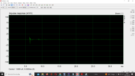
Use a loopback cable from output to the input not in use on your sound card. Switch to dual channel measurement mode, using the loopback signal as timing reference. You’ll get a reliable timing reference and about 3ms offset.
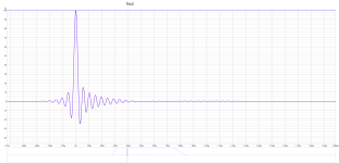
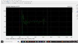
The impulse response looks kinda dirty to me, likely because early reflections or excessive resonances. As long as you cannot distinguish the first reflection peak in the impulse response, you’ll have to work on your physical measurement setup.
The impulse response looks kinda dirty to me, likely because early reflections or excessive resonances. As long as you cannot distinguish the first reflection peak in the impulse response, you’ll have to work on your physical measurement setup.
Can i do like this setting in REW?Use a loopback cable from output to the input not in use on your sound card.
Attachments
My computor is connected to an AV processor (with HDMI), and same computer has USB -mic (umik) and use REW.Use a loopback cable from output to the input not in use on your sound card.
Dont find "dual channel measurement mode" in REW!
And under "Sequentenal channels" i can from REW-manual read:
The Sequential channels mode allows each selected channel to be measured in turn without further intervention. If those channels include the LFE output the Output options below have settings that can be for the LFE only.
When making repeated or sequential measurements a panel is shown with the number of measurements remaining, the name that will be assigned to the next measurement and a pause button that will stop the sequence when the current measurement completes and continue it when un-paused.
About "Loopback" REW say this:
"
So maby i can use some settings instead of "loopback cable from output to the input not in use on your sound card." as you suggest ?
"
Loopback timing reference
There are two loopback options, using the loopback for timing only (Use loopback as timing reference) or using the loopback for both timing and to compensate for the loopback path frequency response Use loopback as cal and timing reference. If the loopback is used to compensate for the loopback path frequency response there are two options. The first is Merge loopback response into IR, which subtracts the loopback path frequency response from the measured response and produces a corresponding impulse response. That works well for full range measurements (sweeps from 0 Hz to half the sample rate) but may have artefacts in the IR if used with sweeps over a limited frequency range. The second is Make calibration data from loopback response, which generates a soundcard calibration data entry for the measurement based on the frequency response measured on the loopback input. In both cases the loopback level at 1 kHz is used to define a 0 dB reference, subject to a check that the loopback response is not more than 20 dB higher than the 1 kHz level anywhere. If that is the case it is offset so that the maximum level (and hence the maximum that will be subtracted from the measurement input response) is 20 dB. If 1 kHz is not within the span of the measurement a frequency in the middle of the measurement span (in a log sense) is used. The distortion results for the measurement input use the response before applying loopback response corrections as the fundamental, otherwise relative distortion figures would be incorrect. Note that using the Use loopback as cal and timing reference option instead of using a soundcard calibration file generated from the measurement input may introduce errors at the frequency extremes where the channel match can degrade."So maby i can use some settings instead of "loopback cable from output to the input not in use on your sound card." as you suggest ?
REW, In1 Mic, Out1 DUT - speaker, In1 loppbacked to OUT2.use loopback as timing reference. Make sure you choose the right channel for timing ref.
In preferences, make sure rew does not automatically move the impulse, like placing the peak to T0.
If all set right, if you measure from 1m, your impulse should be ~ T 3ms.
In preferences, make sure rew does not automatically move the impulse, like placing the peak to T0.
If all set right, if you measure from 1m, your impulse should be ~ T 3ms.
With a USB mic it is not possible to do a dual-channel measurement. There is a trick in REW for "dual" but I haven't tried. With a 2- (or more) channel soundcard 2-ch reference is possible. Then a "passive" mic is used in channel 1 and a loopback signal cable for channel 2. This is to remove delay caused by soundcard/preamp (a usb-mic has internal 1-channel preamp) and to stabilize T=0. 2-ch is helpful when taking measurements for multiway speaker's xo design. It reveals sound time of fly difference from separate drivers.
When we talk about gating it concerns "right window" after the peak impulse of the signal (in one-ch the peak sets T=0 and Ref as same automatically). Longer gating gives better resolution for low frequencies, but also reveals effects of room reflections and modes.
Room Equalization Wizard was designed analyze and eq room response (and subwoofer integration), but several useful features have been added by years gone by. This is why it's default right window length is still 500ms.
Changing REW windowing parameters is very easy, but difficult to explain!
Last edited:
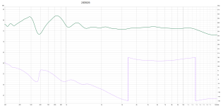
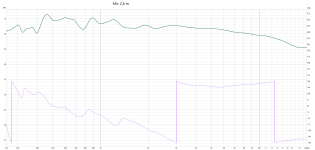
First try to get a decent impulse response, then move mic away. The impulse response will (almost always) get worse when enlarging the distance between DUT and mike.Test to move the mic further away, and fron 1:st test 2,6 meters the "wiggle" calms down a bit.
As for loopback, forget that. I didn’t realize you were using an USB mike. You found the manual, I think you’ll manage.
First try to get a decent impulse response, then move mic away.
Okey, i will do that
")
Question: How can i influence the impulse, if the impule isent good? and what scale-settings ?
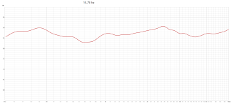
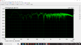
Just to take a break for my medecine-brain, when i get REW going again i test measure from 15 hz in the room (mic still at 2,6 m)
I have almost "full power) at 15 hz.....And that make me glad
...... I lowe a fundamental bass when listening on music!Attachments
Downloaded it and manage to get "something" out of it (maby easyer if you are use to Arta)ARTA is still available
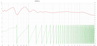
Now mic from 1 meter.
Attachments
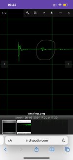
Ok, now, in the impulse window left-click on the graph just left from the impulse rise. Then, right-click just left of the little wiggle somewhat right of the impulse peak. See attached. Then let Arta calculate the response again. Change vertical scale to 5dB per major division.
Btw, you have a disturbing reflection very near to the mike or to the speaker unit. That even smaller wiggle just right of the impulse peak is proof of that. Check your measurement setup. I already said so I think.
Btw, you have a disturbing reflection very near to the mike or to the speaker unit. That even smaller wiggle just right of the impulse peak is proof of that. Check your measurement setup. I already said so I think.
Attachments
Last edited:
I could on the right side in the "impulse-window" click gain min/max, zoom min/max and scroll and offset. (so i get vertical scale 0,5,10, and horizontal to 5,6,7 ms)Ok, now, in the impulse window left-click on the graph just left from the impulse rise. Then, right-click just left of the little wiggle somewhat right of the impulse peak.
But does´t undertand your words
Then let Arta calculate the response again
Attachments
No sirYou are not giving up
.....stubborn as a goatBut learning further one more new program is real hard for me.
Will se if i can find the settings for 12-6 dB and also settings for gate at 6-8,5 ms
You have to click IN the graph. Vertical lines appear as markers. The time block inbetween (aka gate) is the signal you are measuring. Kinda. After setting the gate, choose ‘gated frequency response’. Doing this from my memory, no ARTA running atm… so the exact terms probably are different. But the manual is one of the best.
- Home
- Loudspeakers
- Multi-Way
- 4-800 hz wiggle i my 3 way diy