Hello kind and imaginative helpers,
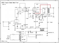
I once published a note to obtain some information about an amp I'm preparing to build. Still not started yet. Bu I do have a few questions regarding a feedback topology. This is a single ended amp using 4d32 output tubes. I include two schematics for analysis and comparison. The first one is 4D32_1.jpg. It's a rather simple single ended fed by a SRPP first stage. This IS the one I plan to build. The second one is another 4D32 SE design; file 4D32_2.jpg.
First question : Both design use very uncommon feedback, tapping on the output stage of the output transformer (highlighted red) instead than on ground. Only on those 4D32 schematics have I seen this arrangement. In other SE circuits, the power tube use an cathode resistor-capacitor coupling arrangement grounded. What is behind this arrangement?
Also note that the bypass capacitor polarity is reversed is from one circuit to the other. On 4D32_1, the negative side of the cap is connected to the cathode while the positive side is on the 4D32_2 schematic. Any explanation on that?
Last question. On 4D32_1.jpg schematic, there is a complex arrangement to provide the screen grid with 336V. Could this have been accomplished by a ultra-linear design coupled with a resistor?
I don't know how those questions sounds to you. As you can see, I'm no expert... far from it. I just want to understand these somewhat unusual circuits.
4D32 sheet :
http://tdsl.duncanamps.com/link.php?target=0025A7DA
Many thanks for your help.
Francois
Attachments

It's basically AC-coupled cathode feedback. The cathode resistor sets the DC operating point for the tube,while the cap couples in some AC feedback from the transformer secondary. This is similar to placing the secondary winding in series with the cathode,but eliminates the DC component.
The capacitor polarity in the first schematic is incorrect,the positive side should go to the cathode,and the negative side to the secondary winding.
The capacitor polarity in the first schematic is incorrect,the positive side should go to the cathode,and the negative side to the secondary winding.
The second schematic appears to be from MJ a Japanese mag...
The issue with both of these schematics, imo, is that you simply can not correct for an output xfmr by wrapping feedback around it. Yes it will flatten the frequency response (until the xfmr just gives up) but it won't correct for the phase shift on the bottom or top and will wreck havoc with a square wave in most instances.
Having said this, it will likely work ok, and sound ok in most applications.
No matter what the quality of any tube amp is somewhat dependent upon the output transformer and not much more (assuming a decent driver circuit, not always the case, but we can just assume, can't we?).
Also a bit depends on the amount of feedback in dB that this arrangement provides. Less is more imho.
_-_-bear
I forgot to say:
the first one has regulated screens.
the second one is driven DC coupled grid and screen!
the second one is all DC coupled.
Note the difference in the primary Z of the output iron?
The second one is driven A2
The tube lineup is non-critical, you don't need a 2C52 on the input, just pick another tube with the same approximate gain and adjust the operating parameters to suit... same with the driver, the 6V6 could be replaced with 6W4, or a 6L6, etc...
You don't really need a 4D32 unless you are looking to handle extra power, and that means even better output iron because the static current is higher than usual...
_-_-bear
The second schematic appears to be from MJ a Japanese mag...
This type of Triode connection was published by RCA transmitting tube manual
as below.
http://our-house.jp/807-5/from-book.gif
G1 and G2 are connected with a resistors of R1, R2 which work as
a reduction of power dissipation of G1's. This Triode connection makes the
tube High-Mu as shown below.
http://our-house.jp/807-5/807t-1k.gif
One problem with this type feedback is that it requires a really large feedback cap. Most designers inject feedback at an earlier, higher impedance point in the circuit. Although that results in a more global feedback topology (shunned by some audiophiles), it can be accomplished with a resistor, rather than a capacitor. I'll add that this circuit should be attempted first without feedback. The 4D32 is, after all, being treated as a quasi-triode. If it turns out not to be sufficiently linear for a no-feedback design, I would try global feedback instead of the cathode feedback shown.
- Status
- Not open for further replies.