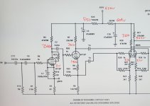
The voltage points seem off. The split-load circuit has 140V at cathode and 233V at plate so the plate resistor should eat up the same amount of voltage that leads to 373V B+ and yet you have a 400V supply. Who ate the 27V? Unless your voltmeter is not high impedance enough, the reading is not right. Maybe a typo?
Not to discourage experimentation, but why not try the Williamson front end as designed? The only change I ever make is to raise the V2 cathode resistor to 680 ohms to let the differential driver stage swing a bit more voltage.
Perhaps measure the output of the phase splitter rather than the output from the first stage, so as to confirm your measurement technique isn't modifying the first stage response due stray anode capacitive loading.
Yes, it’s a Push Pull amplifier. The pain however is (only) in the input stage. I don’t measure a significant difference in frequency response between (1) input stage as described in post 1 and (2) the output measured over my 4 Ohm dummy load.
- Is there a negative feedback loop from the output transformer to this cathodyne circuit?
- What is the value of the grid leak resistors in the stage that comes after this cathodyne circuit?
- How is the output stage biased? Is it cathode biased with individual resistors in each output tube's cathode?
- If yes, what is the value of the cathode resistors, and what is the value of each bypass capacitor for these cathode resistors?
- Do you have a schematic of the whole amplifier you can share? We're missing a lot of information here...
A large decoupling resistor, combined with a too small decoupling capacitor, will cause a boost in the LF response.
Because at low frequencies (where the decoupling capacitor is ineffective), the effective plate resistor is the sum
of the plate resistor and the decoupling resistor.
Because at low frequencies (where the decoupling capacitor is ineffective), the effective plate resistor is the sum
of the plate resistor and the decoupling resistor.
Is there any bypass capacitor at all on the plate supply to the 6SN7 (V1a and V1b)? I don't see one in the schematic. The schematic just shows a 400V voltage source directly connected to the plates of V1a and V2b. is that how it's actually wired up? If so, it would help a lot to be able to see the power supply schematic and voltage readings.
rayma, I missed this comment, which seems to exclude my concern about a measurement issue when probing the anode of the input stage.Yes, it’s a Push Pull amplifier. The pain however is (only) in the input stage. I don’t measure a significant difference in frequency response between (1) input stage as described in post 1 and (2) the output measured over my 4 Ohm dummy load.
As indicated with the concern on the B+ feed to the first stage, Williamson purposefully introduced a 0.6Hz decoupling time constant (33k and 8uF) into the first stage to add some phase margin for better LF stability. Also Williamson did the same for the phase splitter stage, and perhaps more importantly both those stages had similar idle current and signal currents (but antiphase) - which effectively suppressed signal on the upstream decoupling cap and supply. So altering the original design may make it even more important to include LF step compensation (or something equivalent) to achieve unconditional LF stability.

Agreed! When I adapted the Williamson to my needs, I have to make large changes in the coupling cap values to avoid LF instability.
Here's what I came up with: Today, I recorded the voltages of one of the amps...
C5 and C10 are now two 100uF/400V caps || 300k in series instead of a single 47uF 600V.
Here's what I came up with: Today, I recorded the voltages of one of the amps...
C5 and C10 are now two 100uF/400V caps || 300k in series instead of a single 47uF 600V.
Attachments
Last edited:
Gerrit, I'm not saying it is pfb, but it looks like it.Jan,
There is no feedback into the part of the circuit that is shown.
So how could it be influenced by feedback? I don’t get it right now.
There is no feedback added in the entire circuit.
Regards, Gerrit
There's an obvious loop in the amp through the supply with several low passes.
Just looking at a small section makes you miss the big picture.
If you ask for help, show all relevant stuff.
Jan
I appreciate all suggestions very much. This forum is really alive!
I will make some changes and new measurements later today.
Regards, Gerrit
I will make some changes and new measurements later today.
Regards, Gerrit
What folk are trying to say, as politely as possible, is that your very unusual result is likely caused by a very unusual reason, and that the partial schematic and brief description yet available aren't particularly unusual. And that this very unusual reason will be obvious once all details are revealed.
All good fortune,
Chris
All good fortune,
Chris
Maybe the power supply itself has some issue, leading to a response which looks like having too small a decoupling cap. You mentioned a mosfet regulator - which normally looks pretty good if properly designed. But if you did something crazy like using a 1 meg gate stopper the output impedance will suffer at high frequency leading to voltage drop. Measures fine at DC but not AC. That’s one possibility of where an unexpected pole/time constant could come from, and how it might get into the 1KHz-ish region.
I just came back from a few hours of testing in my workshop. I tried all the suggestions I got in this thread and nothing seemed to make a difference (extra series resistors with extra decoupling between the input stage and the PI; using a bench psu for the input stage, etc.).
I was very puzzled and became worried about my incompetence to find what you indicated.
Then I changed my measuring probe (a Velleman 1/10x 60 Mhz. probe) for a Tektronix probe. As far as I can see right now the bode plot is OK and for some reason the Velleman probe gives weird results at low frequencies. I was not aware of that possibility. Does it make sense?
I will do some more testing hopefully tomorrow.
Regards, Gerrit
Attachments

I have to check if my bode plot software (Velleman) has a calibration function. I don’t remember having seen such a property, the software is rather primitive. I will check this with ARTA or Visual Analyzer (spectrum anaylzer) too.
Regards, Gerrit
Regards, Gerrit
I just came back from a few hours of testing in my workshop. I tried all the suggestions I got in this thread and nothing seemed to make a difference (extra series resistors with extra decoupling between the input stage and the PI; using a bench psu for the input stage, etc.).
I was very puzzled and became worried about my incompetence to find what you indicated.
Then I changed my measuring probe (a Velleman 1/10x 60 Mhz. probe) for a Tektronix probe. As far as I can see right now the bode plot is OK and for some reason the Velleman probe gives weird results at low frequencies. I was not aware of that possibility. Does it make sense?
I will do some more testing hopefully tomorrow.
Regards, Gerrit
Oh, good.
- Home
- Amplifiers
- Tubes / Valves
- 6SN7 input stage unexpected frequency response