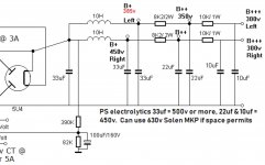
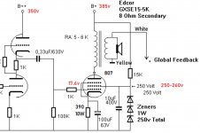
Hello to all. I'm building Triode Dicks 807 single ended amplifier. Pretty much the same one that Blueglow on Youtube built some years back. I've attached the power supply and audio schematics. My question is about the Grid2 250VDC on both the 807's. The schematic shows the B+385 getting tapped to provide the 250VDC after zeners and 15K dropping resistor. The power supply is a split rail for each channel. Are the zeners and 10uF/400V built for each channel, or just once to supply both 807's? Or would it hurt to tap each rail separately for each tube? Thanks for any help. GP53


The way the schematic is drawn points to each channel having its own arrangement for feeding the screen grid. I'm pretty sure that there will be no disadvantages in feedfing each screen grid with its own arrangement, and with the values indicated in the schematic.
Some calculations also make me think that each channel should have its own arrangement for feeding the screengrid:
The voltage drop over the 15K resistor is 385 - 250 = 135 V. So the current through it is 135 / 15K = 9 mA. When feeding only one screen grid, I estimate that without input signal to the 807 the current draw will be about 2.5 mA (taken from the STC Application Report for the 807 from 1954). So in that situation the current through the string of zeners will be 9 - 2.5 = 6.5 mA.
But at full power the screen grid will draw more current than 2.5 mA. I don't have a datasheet of the 807 at hand which states what the the current draw of the screen grid will exactly be at full power but I think if I assume that this current draw doubles to 5 mA that I'm not far off (or atleast that I don't estimate it being too high). This 5 mA stays below the calculated 6.5 mA so even under full power conditions there will still be 1.5 mA of current left for the zener string to do its job of keeping the screen grid voltage stable at 250 V.
So if at full power the screen grid of one 807 draws 5 mA, than the current draw would be 10 mA if you feed the screen grids of two 807's. Note that 10 mA is way higher than the calculated 6.5 mA 'headroom' that the string of zeners has. This means that at those moments of full current draw there would be no current anymore for the string of zeners to do their job. The voltage of 250 V would go down at those moments. The 10 uF capacitor will 'dampen' these effects but I still think that feeding two screengrids from only one zener string with the values indicated in the schematic is a bad idea, since it could well lead to problems/distortion/etc..
It says in the schematic that the zeners should be 1 Watt. The total dissipation in the string under no signal conditions (at these moments the current through the string of zeners is at its highest, so the dissipation is also at its highest) is P = I x V = 0.0065 x 250 = 1.625 Watt. So this means that you can not use only one 250 V zener rated for 1 Watt. It really has to be a string of zeners in which none of the individual zeners will dissipate more than 1 Watt. So the absolute maximum voltage rating of any zener in this string is 150 V (the dissipation at 6.5 mA would than be 0.975 Watt) but I advise you to choose a lower value than this calculated maximum of 150 V.
Mmm, I just noticed that its not so perfect.
In the case of feeding one 807 the current left for the zener string at full power would be 9 - 5 = 4 mA, so not 1.5 mA.
In the case of feeding two 807's the total screen grid current would be 10 mA, so more than the 9 mA running through the 15K resistor. So that's still a no go. The 'headroom' at no signal would be 9 - (2 x 2.5) = 4 mA.
So the outcome is the same, but the way to it was a bit flawed.
I’ll be configuring separate screen supplies using 2 watt 15k dropping resistors along with 56 and 27 volt 1 watt zeners in series to get me to the 250 supply. Along with Solen 10uF/630v caps paralleling the zeners. Thanks again. GP53
Two chokes in the PS is overkill & overweight.
A single choke followed by 330 microF will kill any tendency for cross talk between the channels.
If the source is vinyl then LR separation is limited in any case.
Wikipedia sez 40 db best at mid band.
A single choke followed by 330 microF will kill any tendency for cross talk between the channels.
If the source is vinyl then LR separation is limited in any case.
Wikipedia sez 40 db best at mid band.
- Home
- Amplifiers
- Tubes / Valves
- 807 SE Amplifier Build Grid 2 Question

