Ok so looking at those 2 tubes.
Which one would be the most linear?
The 811 has a High Mu so looks more like higher rp and more distortion.
The 812 is lower Mu so would have lover rp and less distortion.
It will need more clean drive probably.
The 811 was used in the altec 1570
There is also the PFB-150WA and reading on the internet suggests the load impedance of the output was around 1650ohms which is very low I think, Should be more like 5 or 6k
So the question is what to use? 811 or 812.
can they be used around 600v?
The grid will need some heavy positive drive but A source follower can work.
Or else a kathode follower but this will be a small power tube. (6BX7)
It's just thinkering when I was reading about the 811 tube. They look really nice also.
And they are also not that expensive.
811 50mA maximum grid current
typical operation 45mA peak.
812 35mA maximum grid current
typical operation 30mA peak.
Do you want to drive that much current linearly?
It may need to drive up to 30mA or 45mA, and in the opposite direction 0mA in a linear fashion.
There are curves in the RCA transmitting tube book.
Yes, the rp of the 812 is far less than the 811. Just compare the slope of the two plate curves.
Last edited:
I actually had 811A in mind when I started developing this idea: Corona: An Ultra-Low Distortion A2 DHT SE Amp Prototype
They just look so nice....even the price is ok.
It happens that I have a big chunk of output Iron with PP load of 2k2.
So my idea is to use 2 (or3) pairs at a plate voltage of around 600v.
I don't know the maximum voltage these output transformers can handle but 600v looks safe I think.
Secondary is 4/8 or 16 ohm.
In the spec sheet of the 811a there is a class B configuration at 750v with a PP load of 5k1
The spec sheet of the 812 has only configurations of 1kv+ plate voltage.
As the 812 has lower Mu and lower Rp I think something around 600v could be possible using some NFB.
I have to check but it could be that this output transformer has some screen taps. Maybe these could be of use for feedback.
I like the idea you did with the SE 826. Great amount of power.
I have the 811a in spice but not the 812. Using 3 pairs of 811a and enough grid drive (peaks of 100v and 36ma for 1 tube) I could make them drive a PP load of around 1k using some feedback.
Don't know if that is practical and the grids can have this.
Power approaches 300W or almost 100W for 1 pair
As long as the grid can go positive they really deliver.
So far that is all in ltpsice so don't know what this would mean in practice.
As the 812 is lower mu and lower Rp I expect even better.
Do you plan to use DC on the filaments? You need a bit of negative feedback the cancel some hum if using AC filaments.
I have used 811a push pull at times and I think it is the best choice if you need 100+ watts.
I am running horns so I just do not need the power.
For the SE configuration, you can bump up the impedance and get negative feedback by putting the secondary between ground and the cathode side. You may get about 500-1K ohms extra if you have a 16 ohm tap. This works well for the 811a. Sort of what happens with the unity coupled Macintosh amps. The 811a has enough gain that you do not need to worry so much about driving voltage.
Also you should be able to find a smaller driving (20W) mosfet with really low reverse capacitance.
I think the approach I'd take is to look up the max grid dissipation, plot grid power over a complete audio cycle at max power and estimate area under the curve.
Now you know average grid power (at max output). If this is within limits of the grid max dissipation you should be safe to build the amp and test at full power.
If not, you may still be able to build the amp (since music crest factor will come into play) but you have to be careful not to test with continuous high power sine waves, nor can you allow the amp to break into oscillations.
My gut feeling is that you are probably fine since these tubes were made for positive grid drive but you would want to do your homework before starting just to make sure.
So you have 2.2K output iron, what kind of power is said iron good for? If they are 200W transformers then sure, 4x811A per channel may be the way to go. If they are 50W 2.2K output transformers, then this doesn't make a ton of sense.
they are rated 240W (30Hz to 15Khz) and 120W (20Hz to 20Khz)
So could be a real possibility.
I also found in the ratings that the Isolation is good for 3kV.
Don't want to push things but there is still some room for more.
So could be a real possibility.
I also found in the ratings that the Isolation is good for 3kV.
Don't want to push things but there is still some room for more.
Yeah, go for it! Consider using a few SMPS modules to heat all those tubes. I would go for the 811, as they are far easier to get and still in production.
Last edited:
Aside from active production of 811as, I know there are quite a few 811a push-pull pairs in use at some drive in theaters due to the coronavirus.
I could be wrong but if it is rated 120w => 20Hz, 240W => 30Hz does that mean it could handle close to 500w at 40Hz? (as long as the isolation holds ofcourse....)
When I raised the plate voltage to 800v and use the 16ohm tap with 8 ohm speakers (= resulting in a pp load of 1k1) I am getting close to 500w at clipping using 3 pairs of 811a
Something tells me this is to good to be true. (transformer losses etc....)
I don't think it would be wise to push the plate voltage further then 800v (isolation)
Grid current peaks at 40mA and 110V (4.4W) for 1 tube
Each tube dissipates an average of 40w-50w.
Gonna see if I have some suitable power transformer to try this on the lower voltage (600v) first and see what the result is
The grid will need some heavy positive drive but A source follower should work
My own 811a project is looking for a driver. I want to go solid state with this.
I been all over this forum most of the night looking for one associated with the 811A and there is much talk about it but no real schematic reference.
I am running an 811A RCA tube with the Hammond 1628SEA audio transformer. My power supply can go 800 V.
I was thinking IRF 840 FET but I have questions. Should I use a current limiter ? Or not ? I seen both suggested.
Is there a FET follower (module) commercially available ?
Does a schematic of this application exist or do I need to design it myself ?
Will this application create excessive heat ?
Is there any design notes available for the FET source follower grid drive available ?
Any help would be appreciated.
Thanks, newbie member.
Dj
I am running an 811A RCA tube with the Hammond 1628SEA audio transformer. My power supply can go 800 V.
1628SEA is a 5k output transformer. Therefore the optimum plate voltage is 500 V or below.
I have built a 811A SE amplifier years ago. I used 10k Edcor OPT with 750 V as +Ub.
The driver stage was soviet twin triode 6N6P, one halve/channel.
I have no experience with NFET driver, but as it is a source follower, the case should be easy to design.
Is there any design notes available for the FET source follower grid drive available ?
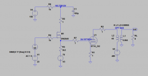
I made a very quick simulation with attached driver circuit. Basically this or a modified version is what is needed.
Attachments
That is great. Thank you very much.
I am going to order some parts and mock this up and take some measurements.
I am going to order some parts and mock this up and take some measurements.
PP 811A
I searched the forums and stumbled on this thread. I remembered that long time ago (1995) I had made a pair of PP 811A for my son's band playing in our basement. I have never really measured these amps but heard the "noise" from the basement and thought they worked well! The OP Xformer I used was a Mk VI Dynaco (454355) with sec wired in order to double the prim Z.
I join the diagram and can add that the input and phase split sections were modified but I cannot remember how! The sec. section of the OP Xformer is wired for 8 ohm on 0 - 4 (speaker) and 8 ohm resistor on 4-16. There was CFB and cathode followers 6BL7 GTA. The 811A tubes ran on bias with 40 mA.
Attachments
- Home
- Amplifiers
- Tubes / Valves
- 811a or 812