I added two 5.25 inch drivers on sides of the 15inch driver main cabinet. I used data of this inexpensive driver that is available locally:
https://www.electrocarts.in/product/peerless-by-tymphany-full-range-fsl-0512r01-08/
It looks like it helps with controlling the directivity above 200Hz a lot.. Cost is an extra DSP+amplifier channel
Here is a simulation with and without the side drivers
With side drivers (just one possibility. The pattern above 200Hz can be significantly changed using the side drivers)


Without side drivers


Is it worth following the above approach and adding two of those small drivers at the sides (in small sealed boxes)? 🤔
https://www.electrocarts.in/product/peerless-by-tymphany-full-range-fsl-0512r01-08/
It looks like it helps with controlling the directivity above 200Hz a lot.. Cost is an extra DSP+amplifier channel
Here is a simulation with and without the side drivers
With side drivers (just one possibility. The pattern above 200Hz can be significantly changed using the side drivers)
Without side drivers
Is it worth following the above approach and adding two of those small drivers at the sides (in small sealed boxes)? 🤔
Attachments
Just noticed a mistake in the simulation settings. I had kept the listening distance as 1m earlier instead of the standard 2m.
Now I have changed it and here is a comparison with & without side drivers
Without side drivers

With side drivers

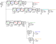
Filter settings with side drivers

Now I have changed it and here is a comparison with & without side drivers
Without side drivers
With side drivers
Filter settings with side drivers
There is little difference in radiation to the front and sides but rearward is another story.
The question is whether the side drivers are needed to eliminate a front wall reflection null.
If so, wouldn't side vents plus Basotect do just as well?
If the only reason for side drivers or vents is rearward directivity, you may be able to do that with the rear woofer, allowing it to play up to 250 Hz or so and tuning its phase and delay to optimize directivity. My simulation experience with rear woofer cardioid is it works well, but only up to 200 or 300 Hz. Might work higher for your case because your cabinet isn't very deep.

@nc535. The issue with side vents + basotect is the problem with preciseness in control compared to an active DSP able channel using separate drivers. The Basotect thing just behaves like it wants to. The other issue is the loss of low frequency extension of the 15inch driver. I will definitely have to EQ it up by some dB to get it to meet the bottom woofer as we want. Also I am having difficulties to get the two 15 inch drivers alone to do the pattern control work above 200Hz. I fact the cost to buy basotect in the kind of sheets that I had bought earlier now well exceed the cost of 4 of these drivers 😀 (the distributor of that basotect foam here now has a minimum quantity for online orders)
The small drivers seem to be giving a lot more flexibility to the whole setup. For example I can get much wider band hyper cardioidish radiation with the side drivers by just tweaking the DSP channel connected to them. It can also affect the frontal radiation to some extent.
Without side drivers

With side drivers


Another example with side drivers

I have attached the VituixCAD project files with this post 🙂
Plus the whole thing looks like this. Its now a minion with two ears as well.. 😀

The small drivers seem to be giving a lot more flexibility to the whole setup. For example I can get much wider band hyper cardioidish radiation with the side drivers by just tweaking the DSP channel connected to them. It can also affect the frontal radiation to some extent.
Without side drivers
With side drivers
Another example with side drivers
I have attached the VituixCAD project files with this post 🙂
Plus the whole thing looks like this. Its now a minion with two ears as well.. 😀
Attachments
I like the look with the side drivers too, and there is no doubt they give you the most control.
Have you discovered that Vituix PEQs can be configured for phase equalization?
I have found them useful for side woofer cardioid simulation optimization in the past as the optimum delay varies with frequency.
Have you discovered that Vituix PEQs can be configured for phase equalization?
I have found them useful for side woofer cardioid simulation optimization in the past as the optimum delay varies with frequency.
@nc535: Yes.. I have found out about the VituixCAD parametric phase EQ a while back.
I use them in my FIR filter-based crossover for the passive cardioid computer speakers (The ones with basotect and Sica coax) that I now have.. 🙂
I also tried using Phase EQ on this current speaker design but have been more careful since somebody once told me in some context to be very careful with phase (alone) EQ at low frequencies.. So I have not been using them extensively (I was only trying to vary the phase between -30 & +30 degrees and lower Q values). It did give me 1+ dB more attenuation of radiation to the back. But when I saw the side driver-based responses without even adding an explicit delay, I stopped playing around with it. 😀
Before you go too far put the waveguide in and see what sort of directivity you need to match. The waveguide DI is quite high and you may well need the rising DI of the plain woofer in the box to rise up and meet the waveguide with a smooth transition.
Speakers like the 8c and the M3 use lower directivity waveguides so they match the lower directivity pattern of the cardioid woofer section.
I ran through this whole process before and found that the side drivers did not really offer anything worth the cost and complexity they bring when a higher DI waveguide is planned.
I would agree about the use of significant phase correction, that just indicates that the acoustic design is wrong. If used, side drivers need to have about 1/2 the Sd of the front woofer or more to provide the cancellation without adding more issues themselves.
^ I agree
Basotect was what was needed with your Sica coax in the kind of configuration you used but it's not sure it is the material you'll need with an hypothetical cardioid passive 15"...
Kimmosto used other materials in his numerous experimental built he documented on his personal site of years ago. In fact it'll depend of the global approach: where slots are located, depth of box, distance to the driver...
Please apologize if i keep on repeating myself about Martinj but look for D&D patents, 8c is only one of the products they offer, there is other cardio designs with ( way) bigger drivers and different field of application ( P.A.) worth a read imho.
I find NC535 previous comment in post #1623 about your goal with cardio worth thinkin about too.
I'am not trying to discourage you about active cardioid approach Vineeth but passive is an elegant answer from ( my) engineering point of view.
The real limitations are the lower freq you need to control ( here active offer some benefits as explained by NC535 up to 200hz- and why most commercial cardio 'sub' offering is based upon it) and the need for experimentation/prototype to find the right 'material' in relation to the design.
As for the need for eq: with lower diameter drivers and low efficiency i agree it's a two edged sword as you run into risk of higher (audible) distortion with a bit of output level request but with a 15" it's less true if the driver is not anemic about efficiency.
@nc535. The issue with side vents + basotect is the problem with preciseness in control compared to an active DSP able channel using separate drivers. The Basotect thing just behaves like it wants to. The other issue is the loss of low frequency extension of the 15inch driver. I will definitely have to EQ it up by some dB to get it to meet the bottom woofer as we want. Also I am having difficulties to get the two 15 inch drivers alone to do the pattern control work above 200Hz. I fact the cost to buy basotect in the kind of sheets that I had bought earlier now well exceed the cost of 4 of these drivers 😀 (the distributor of that basotect foam here now has a minimum quantity for online orders)
Basotect was what was needed with your Sica coax in the kind of configuration you used but it's not sure it is the material you'll need with an hypothetical cardioid passive 15"...
Kimmosto used other materials in his numerous experimental built he documented on his personal site of years ago. In fact it'll depend of the global approach: where slots are located, depth of box, distance to the driver...
Please apologize if i keep on repeating myself about Martinj but look for D&D patents, 8c is only one of the products they offer, there is other cardio designs with ( way) bigger drivers and different field of application ( P.A.) worth a read imho.
I find NC535 previous comment in post #1623 about your goal with cardio worth thinkin about too.
I'am not trying to discourage you about active cardioid approach Vineeth but passive is an elegant answer from ( my) engineering point of view.
The real limitations are the lower freq you need to control ( here active offer some benefits as explained by NC535 up to 200hz- and why most commercial cardio 'sub' offering is based upon it) and the need for experimentation/prototype to find the right 'material' in relation to the design.
As for the need for eq: with lower diameter drivers and low efficiency i agree it's a two edged sword as you run into risk of higher (audible) distortion with a bit of output level request but with a 15" it's less true if the driver is not anemic about efficiency.
Last edited:
I took a break from everything and went exploring what happened in 5th century AD for a couple of days.. 😀


Back to speakers.. 😀
This is the kind of unnormalized polar plot I got from the SICA coax system (restricted to 30dB dynamic range on y axis)

Probably some of that nice, smooth curves have to do with lack of more resolution with gated measurements.
But my objective with this big system was to get a similar polar plot with a few improvements
1) System capable of more dynamics/SPL (100dB SPL+ at 2m away)
2) A bit more extension of controlled directivity to lower frequency range, like, to 100Hz
3) A bit more smoother looking high frequency extension (avoiding the obvious issues that arise with a coax driver)
4) Overall, relatively thin speaker cabinet profile, intended for placement close to the front wall and something that is modular, relatively easy to measure with options to change speaker cabinet concept in future (if needed) like I did with my main system.
So far, with just diffraction simulation-based plots, this is how the lower end of the spectrum (with the two 15inch drivers in sealed boxes and DSP looks like)


I traced the EXAR 400 horn responses from the datasheet (predicted responses upto 90degrees, normalized)


There is some mismatch between the VituixCAD SP DI values and the datasheet, which can be seen upon comparing the above plot with the below one. The datasheet directivity is about 2dB higher especially around the 1kHz region compared to the above directivity based on traced curves.

I also tried to get a prototype crossover in place with the woofer system and the horn, but there are some issues with it

Wierdly, the woofer system directivity also now came down by 2dB making all curves look a little mismatched and a big directivity step around the 700Hz region.
I guess all these issues are due to the non availability of data/measurements of the horn, which I am yet to do..
But looking at this plot from above
and the data sheet SPDI of the horn

I think a good directivity match can be obtained somewhere in the 600Hz to 1kHz region.. 🙂
But my concern is whether I will be able to achieve anything close to this pattern width, especially the 300Hz to 1kHz region. Here there is 20dB to 30dB attenuation of energy in the beyond 135degrees of angle region
whereas with the current woofer system directivity, I see 12dB attenuation at best

This is the kind of unnormalized polar plot I got from the SICA coax system (restricted to 30dB dynamic range on y axis)
Probably some of that nice, smooth curves have to do with lack of more resolution with gated measurements.
But my objective with this big system was to get a similar polar plot with a few improvements
1) System capable of more dynamics/SPL (100dB SPL+ at 2m away)
2) A bit more extension of controlled directivity to lower frequency range, like, to 100Hz
3) A bit more smoother looking high frequency extension (avoiding the obvious issues that arise with a coax driver)
4) Overall, relatively thin speaker cabinet profile, intended for placement close to the front wall and something that is modular, relatively easy to measure with options to change speaker cabinet concept in future (if needed) like I did with my main system.
So far, with just diffraction simulation-based plots, this is how the lower end of the spectrum (with the two 15inch drivers in sealed boxes and DSP looks like)
I traced the EXAR 400 horn responses from the datasheet (predicted responses upto 90degrees, normalized)
There is some mismatch between the VituixCAD SP DI values and the datasheet, which can be seen upon comparing the above plot with the below one. The datasheet directivity is about 2dB higher especially around the 1kHz region compared to the above directivity based on traced curves.
I also tried to get a prototype crossover in place with the woofer system and the horn, but there are some issues with it
Wierdly, the woofer system directivity also now came down by 2dB making all curves look a little mismatched and a big directivity step around the 700Hz region.
I guess all these issues are due to the non availability of data/measurements of the horn, which I am yet to do..
But looking at this plot from above
and the data sheet SPDI of the horn
I think a good directivity match can be obtained somewhere in the 600Hz to 1kHz region.. 🙂
But my concern is whether I will be able to achieve anything close to this pattern width, especially the 300Hz to 1kHz region. Here there is 20dB to 30dB attenuation of energy in the beyond 135degrees of angle region
whereas with the current woofer system directivity, I see 12dB attenuation at best
Attachments


Could you explain a little more about this 1/2 Sd requirement?If used, side drivers need to have about 1/2 the Sd of the front woofer or more to provide the cancellation without adding more issues themselves.
@krivium: Thanks.
I am going through Dutch & Dutch patents to try and understand their work. The motivation to use a woofer at the back is partly from their work 🙂
This also helps with getting some directivity control in the 100Hz to 300Hz region with DSP tweaks as per @fluid's ideas
The front woofer pattern control capability using passive cardioid/active cardioid configuration is still something I am thinking about and need some help to get more clarity. 🤔
Those buildings and scenery are amazing. Great photos! 😲
Since you are still thinking about passive cardioid I'll include the Sigberg Manta measurements from Spinorama dot org that uses the same coax driver you used in your 3-way coax cardiod design. Notably, capable of max SPL of 122dB with low distortion, which is one aspect you've been analyzing in your woofer design concepts. So at least you know it's possible with passive. Here's the design explanation and specs from Sigberg (added the specification text below the measurements): https://www.sigbergaudio.no/products/sigberg-audio-manta-1-active-speakers


And the measurements posted on Spinorama:

Horizontal


Vertical


And the specs:
Frequency response with Sigberg Audio subwoofers:
25-20,000hz +/-2.5dB
20-20,000hz (typical in-room response)
Distortion / Noise:
<0,5% THD @96dB/1m (per speaker)
Internal hiss/noise inaudible at >30cm / 1 ft.
Max SPL@1m (CTA-2034-A weighted pink noise):
122dB (per speaker)
Recommended listening distance:
1.5-8 meters (5-26 feet)
Cardioid dispersion characteristics (120-180°):
~100-500hz: 10-12dB attentuation
~500hz-1khz: 16-20dB attentuation
~1-5khz: 25dB attentuation
Type
3-way (4-way with sub)
Asymmetric 1st/3rd order linear phase crossover
Dual cardioid cabinet with acoustic vents
Drivers / Amplifier:
12" midbass, 5.5" midrange, 1" silk dome tweeter.
Active 3-channel Hypex nCore class D amplifier with DSP (600W per speaker)
Equalizer / Room correction:
Manual EQ, 9-band parametric
Factory Presets: +0dB, +2dB, -2dB Treble tilt
Inputs:
Analog: RCA, XLR balanced (in/through)
Digital: Optical, Coaxial/SPDIF (in/through), AES (in/through)
Latency / processing time:
0.35ms (Analog inputs) / 1.8ms (digital inputs)
Dimensions (WHD):
360x600x350 mm
Total height on included stands: 107cm (42 inches)
Accessories:
Power cable (EU/US), USB-cable, magnetic detachable grilles
Weight:
25kg / speaker
Shipping weight including stands: 64kg
Placement:
Unique black MANTA stainless steel stand (included), tilting the speaker 4 degrees. Stands rests on silicone based isolation / absorbtion feet.
Recommended distance from wall: 10-50 cm.
Since you are still thinking about passive cardioid I'll include the Sigberg Manta measurements from Spinorama dot org that uses the same coax driver you used in your 3-way coax cardiod design. Notably, capable of max SPL of 122dB with low distortion, which is one aspect you've been analyzing in your woofer design concepts. So at least you know it's possible with passive. Here's the design explanation and specs from Sigberg (added the specification text below the measurements): https://www.sigbergaudio.no/products/sigberg-audio-manta-1-active-speakers
And the measurements posted on Spinorama:
Horizontal
Vertical
And the specs:
Frequency response with Sigberg Audio subwoofers:
25-20,000hz +/-2.5dB
20-20,000hz (typical in-room response)
Distortion / Noise:
<0,5% THD @96dB/1m (per speaker)
Internal hiss/noise inaudible at >30cm / 1 ft.
Max SPL@1m (CTA-2034-A weighted pink noise):
122dB (per speaker)
Recommended listening distance:
1.5-8 meters (5-26 feet)
Cardioid dispersion characteristics (120-180°):
~100-500hz: 10-12dB attentuation
~500hz-1khz: 16-20dB attentuation
~1-5khz: 25dB attentuation
Type
3-way (4-way with sub)
Asymmetric 1st/3rd order linear phase crossover
Dual cardioid cabinet with acoustic vents
Drivers / Amplifier:
12" midbass, 5.5" midrange, 1" silk dome tweeter.
Active 3-channel Hypex nCore class D amplifier with DSP (600W per speaker)
Equalizer / Room correction:
Manual EQ, 9-band parametric
Factory Presets: +0dB, +2dB, -2dB Treble tilt
Inputs:
Analog: RCA, XLR balanced (in/through)
Digital: Optical, Coaxial/SPDIF (in/through), AES (in/through)
Latency / processing time:
0.35ms (Analog inputs) / 1.8ms (digital inputs)
Dimensions (WHD):
360x600x350 mm
Total height on included stands: 107cm (42 inches)
Accessories:
Power cable (EU/US), USB-cable, magnetic detachable grilles
Weight:
25kg / speaker
Shipping weight including stands: 64kg
Placement:
Unique black MANTA stainless steel stand (included), tilting the speaker 4 degrees. Stands rests on silicone based isolation / absorbtion feet.
Recommended distance from wall: 10-50 cm.
You can't mix different types of directivity data, it is either +- 90 or +-180, if you try and mix it as you have it doesn't work and the display is wrong.
You can see clearly in the separate plots that side vents or drivers will not do anything helpful with a higher directivity waveguide. You still want to mix a 15" driver and horn in the same way you would without the rear woofer. The rear woofer just helps to give some directivity control to a lower frequency than the box would do by itself.
If you want flat lower DI all the way up then the side vents/drivers and a wider pattern waveguide will get you there.
1/2 Sd is to allow the cancellation drivers to not be struggling to compete with the front woofer. Like anything you can use whatever you want but going less than 1/2 will mean the side drivers giving up before the front one. Ideal is to have the same drivers on side and front, but this has it's own challenges with large drivers.
It really is possible to "patent" anything if you are clever enough with the definitions in the claims.
Thanks @CinnamonRolls for the data on Sigberg Manta..🙂
The Manta data has convinced me that I don't need to go passive cardioid with this build.
I am now convinced of @fluid's logic about the 15inch driver's directivity capabilities and how it matches with this particular waveguide 🙂
Just trying to compare the SPDI between the Manta & the proposed dual woofer configuration below
Sigberg Manta spin data plot

Corresponding plot for proposed dual woofer setup

I am interested in the SPDI in the above 2 plots
The Manta directivity doesn't climb above 4dB until above 400Hz, whereas with the proposed set up, that 4dB is already achieved at 100ish Hz and stays constant for a while before the woofer beaming takes over.
Construction-wise, the dual-woofer concept needs none of the complicated prototyping needed for the cardioid. 🙂
So, just the two woofer boxes alone it is for this speaker. 🙂
(Someday, if at all needed, I can also try a GGNTKT M1-like topmodule or a larger coax topmodule (for an overall lower directivity system) as well this way.. 😉 😀 😀)
In the meanwhile, I also found some 3rd party review of the subwoofer driver that I am considering for this speaker 🙂
https://josephcrowe.com/blogs/news/sb-acoustics-nero-15sw800-with-cabinet-no-1798
It seems like he thinks that it is a nice driver for subwoofer application (although in a completely different type of cabinet than the one I am thinking)
I may also be able to get the https://josephcrowe.com/blogs/news/beyma-15lx60v-with-cabinet-no-1798 with a lot more effort in contacting the right people, but I am tending towards the SB driver for now 🙂
The Manta data has convinced me that I don't need to go passive cardioid with this build.
I am now convinced of @fluid's logic about the 15inch driver's directivity capabilities and how it matches with this particular waveguide 🙂
Just trying to compare the SPDI between the Manta & the proposed dual woofer configuration below
Sigberg Manta spin data plot
Corresponding plot for proposed dual woofer setup
I am interested in the SPDI in the above 2 plots
The Manta directivity doesn't climb above 4dB until above 400Hz, whereas with the proposed set up, that 4dB is already achieved at 100ish Hz and stays constant for a while before the woofer beaming takes over.
Construction-wise, the dual-woofer concept needs none of the complicated prototyping needed for the cardioid. 🙂
So, just the two woofer boxes alone it is for this speaker. 🙂
(Someday, if at all needed, I can also try a GGNTKT M1-like topmodule or a larger coax topmodule (for an overall lower directivity system) as well this way.. 😉 😀 😀)
In the meanwhile, I also found some 3rd party review of the subwoofer driver that I am considering for this speaker 🙂
https://josephcrowe.com/blogs/news/sb-acoustics-nero-15sw800-with-cabinet-no-1798
It seems like he thinks that it is a nice driver for subwoofer application (although in a completely different type of cabinet than the one I am thinking)
I may also be able to get the https://josephcrowe.com/blogs/news/beyma-15lx60v-with-cabinet-no-1798 with a lot more effort in contacting the right people, but I am tending towards the SB driver for now 🙂
These were my simulations for a 15" woofer with passive-cardioid side vents: https://www.diyaudio.com/community/...-design-the-easy-way-ath4.338806/post-7246372
I can't see a reason why you could not achieve such results, as you were able to do it with the small coax.
Between 600 - 800 Hz it seems like a close-enough match to me.
I can't see a reason why you could not achieve such results, as you were able to do it with the small coax.
Between 600 - 800 Hz it seems like a close-enough match to me.
Thanks @mabat for the suggestion.. 🙂
At this point, I am trying to build a modular system that will serve as a base for further explorations in future.
In that sense, I think the two-sealed-box solution will help me reuse the 2 boxes (per side) in different configurations in future.
For example,
1) I might be able to experiment with a full range cardioid sometime by placing the 2 boxes back to back and DSP EQing them appropriately and using an appropriate top module
2) I can have a dual woofer system with a big 12inch coax (in a cardioid enclosure like I have for the SICA coax now) like this one: https://en.toutlehautparleur.com/br...xial-speaker-bms-12c382-8-16-ohm-12-inch.html on top of the dual woofer or a single woofer system.
I love my SICA coax cardioid system in its near-field application so much that I keep playing music on it repeatedly. 😀 But the SICA system just doesn't have the sheer muscle to replace/compete with the dynamics of my main system.. Even then, my current main Satori woofers-based system is lying idle these days.
So, there is a lot of motivation to try out a big coax driver in the cardioid enclosure as part of the main system.
3) I can have a synergy horn on top of the dual woofer system at the bottom
4) I can have a GGNTKT M1-like top module if needed
5) In an extreme abuse of system configuration, I can have 2 or even 4 of these shallow boxes as spatially distributed subwoofers with another of the above systems playing as mains etc.. 😀
This is part of my motivation to go with this two-sealed-box solution for now.
The other part of the motivation comes from the following.
I traced the predicted sound power directivity of the dual woofer system (red colour) and the EXAR 400 waveguide (green) below. Please don't mind the black summed response and the phase indexing on the y-axis on the right side. Please interpret the values on the y-axis as sound power DI (All this because I abused the SPL magnitude plot of VituixCAD to show directivity 😀)

Without any explicit adjustment, I can't hope for a better directivity match in the 500 to 1kHz range. The EXAR 400 + dual woofer system look like a match made in heaven.. 😀
The figure below shows the SPDI for the BEE enclosure (red) and the EXAR 400 waveguide (green).

Obviously, the higher directivity of the BEE enclosure has its own advantages and the slight DI mismatch everywhere is probably very workable in a crossover design, but it takes away most of the above-mentioned flexibilities with system configuration or so I feel..
So, I am going to build the dual woofer sealed box system now (If everything in life goes well) 🙂
At this point, I am trying to build a modular system that will serve as a base for further explorations in future.
In that sense, I think the two-sealed-box solution will help me reuse the 2 boxes (per side) in different configurations in future.
For example,
1) I might be able to experiment with a full range cardioid sometime by placing the 2 boxes back to back and DSP EQing them appropriately and using an appropriate top module
2) I can have a dual woofer system with a big 12inch coax (in a cardioid enclosure like I have for the SICA coax now) like this one: https://en.toutlehautparleur.com/br...xial-speaker-bms-12c382-8-16-ohm-12-inch.html on top of the dual woofer or a single woofer system.
I love my SICA coax cardioid system in its near-field application so much that I keep playing music on it repeatedly. 😀 But the SICA system just doesn't have the sheer muscle to replace/compete with the dynamics of my main system.. Even then, my current main Satori woofers-based system is lying idle these days.
So, there is a lot of motivation to try out a big coax driver in the cardioid enclosure as part of the main system.
3) I can have a synergy horn on top of the dual woofer system at the bottom
4) I can have a GGNTKT M1-like top module if needed
5) In an extreme abuse of system configuration, I can have 2 or even 4 of these shallow boxes as spatially distributed subwoofers with another of the above systems playing as mains etc.. 😀
This is part of my motivation to go with this two-sealed-box solution for now.
The other part of the motivation comes from the following.
I traced the predicted sound power directivity of the dual woofer system (red colour) and the EXAR 400 waveguide (green) below. Please don't mind the black summed response and the phase indexing on the y-axis on the right side. Please interpret the values on the y-axis as sound power DI (All this because I abused the SPL magnitude plot of VituixCAD to show directivity 😀)
Without any explicit adjustment, I can't hope for a better directivity match in the 500 to 1kHz range. The EXAR 400 + dual woofer system look like a match made in heaven.. 😀
The figure below shows the SPDI for the BEE enclosure (red) and the EXAR 400 waveguide (green).
Obviously, the higher directivity of the BEE enclosure has its own advantages and the slight DI mismatch everywhere is probably very workable in a crossover design, but it takes away most of the above-mentioned flexibilities with system configuration or so I feel..
So, I am going to build the dual woofer sealed box system now (If everything in life goes well) 🙂
Last edited:
You could also look at the ATH-280EX (at my website), which has a wider directivity. I designed that waveguide as an all-rounded, partly with cardioid speakers in mind. That should be capable of 700 - 800 Hz without problems and the DI is very convenient, IMO:

Thanks @mabat. I had the 280EX horn in mind initially. But then I wanted to try out a bigger-sized horn first. Hence, went with the EXAR 400 first.
Based on the results I may want to try out an even bigger horn.. 🙂
In fact I have the EXAR 400 printed in ABS waiting to be assembled at home 🙂

I just haven't got the time yet to assemble it all together and take a measurement with my BMS 4550 CD, with all other things going on in life at the moment, most importantly a change in my day job profile
I hope to assemble this horn and take some measurements soon..
Based on the results I may want to try out an even bigger horn.. 🙂
In fact I have the EXAR 400 printed in ABS waiting to be assembled at home 🙂
I just haven't got the time yet to assemble it all together and take a measurement with my BMS 4550 CD, with all other things going on in life at the moment, most importantly a change in my day job profile
I hope to assemble this horn and take some measurements soon..
If you only knew how many boxes like this I have at home... 🙂
The prints look very good indeed. Good luck assembling it!
The prints look very good indeed. Good luck assembling it!
This is very close to my own thinking, that it is a flexible option that works well with a lot of top module options.This is part of my motivation to go with this two-sealed-box solution for now.
Something else you can try out is to let the directivity rise up gently over the whole range (more similar to mabat's example), instead of there being a plateau.
One thing to remember when comparing db's of DI is that anything with a rear facing component either driver or port will create negative directivity in the plot. It's important to look at the pattern as well, the DI could be confusing but the pattern shape should be easier to see.
- Home
- Loudspeakers
- Multi-Way
- A 3 way design study