With the exception of socketing for the OpAmps on Tuscon, I finished up my IPSs.
My primary thought is Mark’s build notes are spot on. I had a ball building the small boards. It was very rewarding.
Tucson was drama-free. I will be putting in sockets to make it easier to explore different OpAmps. I’m waiting on the parts. Fun!
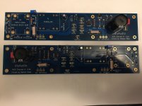
Mountain view – I was careful to orient the LEDs the proper direction and follow the notes. I also triple-checked the diodes and the transistor orientations. Again, drama free.
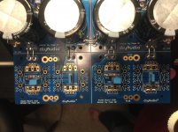
Norwood – Fortunately, I had done some SMD soldering before. I admit that I’m not thrilled with the visual outcome. My boards won’t win any beauty contests. Some will notice specifically that U5 on one board is definitely not ideal. However, I examined all joints under 10x magnification, and I followed up with a continuity check. It's secure to all the pads. I used a finer solder than for the through-hole work and a fine conical tip. Everyone has their own preferences. Mark lists some examples of things to make life much easier over in the main M2x thread. I have to use fairly high magnification (3.5x over my readers) and get close to the work. Overall, the proof will be if it functions properly, but it was fairly drama free. I continue to learn. I learned that I get parts aligned much better if I am directly over the board looking straight down vs. at an angle in front of the board. See U5...
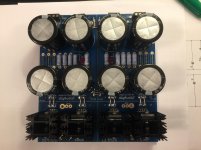
Austin – There was a bit of anxiety with Austin. I followed Mark’s notes, which made it drama free, but there was a lot of checking and double-checking the transistors. Mine had two different orientations (Q1-Q4 vs Q5,Q6). I looked up the spec sheets and drew the orientations on the parts bags. My personal technique was to figure out whether the middle leg needed to be bent to the front or the rear of the part, bend the leg, and then orient the part accordingly into the holes.
I soldered the resistors first. If I had it to do over again, I’d put in the small caps and the ICs first. It didn’t cause any issues, but they sit lower on the board than the resistors. I was also very careful in preventing and checking/inspecting for bridges. The pads on the back of the board for the resistors are quite close together. I used the same fine solder and conical tip I used for the SMD work on Norwood. It allowed me to control the feed of the solder a bit better and (mostly) prevent overdoing it.
I can’t wait to try them out. I am researching how to properly test them before installation into the amp. For Austin, Mark recommends a process, but I need to learn a bit more. Any time I read “catch fire”, I pause.
Next up is the amp boards.
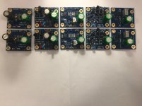
I took pictures along the way of all the boards, but here is one glamor shot of the pretty maids all in a row. OK, two rows.
My primary thought is Mark’s build notes are spot on. I had a ball building the small boards. It was very rewarding.
Tucson was drama-free. I will be putting in sockets to make it easier to explore different OpAmps. I’m waiting on the parts. Fun!
Mountain view – I was careful to orient the LEDs the proper direction and follow the notes. I also triple-checked the diodes and the transistor orientations. Again, drama free.
Norwood – Fortunately, I had done some SMD soldering before. I admit that I’m not thrilled with the visual outcome. My boards won’t win any beauty contests. Some will notice specifically that U5 on one board is definitely not ideal. However, I examined all joints under 10x magnification, and I followed up with a continuity check. It's secure to all the pads. I used a finer solder than for the through-hole work and a fine conical tip. Everyone has their own preferences. Mark lists some examples of things to make life much easier over in the main M2x thread. I have to use fairly high magnification (3.5x over my readers) and get close to the work. Overall, the proof will be if it functions properly, but it was fairly drama free. I continue to learn. I learned that I get parts aligned much better if I am directly over the board looking straight down vs. at an angle in front of the board. See U5...
Austin – There was a bit of anxiety with Austin. I followed Mark’s notes, which made it drama free, but there was a lot of checking and double-checking the transistors. Mine had two different orientations (Q1-Q4 vs Q5,Q6). I looked up the spec sheets and drew the orientations on the parts bags. My personal technique was to figure out whether the middle leg needed to be bent to the front or the rear of the part, bend the leg, and then orient the part accordingly into the holes.
I soldered the resistors first. If I had it to do over again, I’d put in the small caps and the ICs first. It didn’t cause any issues, but they sit lower on the board than the resistors. I was also very careful in preventing and checking/inspecting for bridges. The pads on the back of the board for the resistors are quite close together. I used the same fine solder and conical tip I used for the SMD work on Norwood. It allowed me to control the feed of the solder a bit better and (mostly) prevent overdoing it.
I can’t wait to try them out. I am researching how to properly test them before installation into the amp. For Austin, Mark recommends a process, but I need to learn a bit more. Any time I read “catch fire”, I pause.
Next up is the amp boards.
I took pictures along the way of all the boards, but here is one glamor shot of the pretty maids all in a row. OK, two rows.
Attachments
I got the replacement parts for CX-1 and CX-2, so I was able to finish up my power supply.
Again, thanks very much to @6L6 for the assistance with the snubber values. Overall, there were no challenges with the overall build execution. It was the planning and selection of parts. I learned quite a bit. I have it on my upgrade / "try this" list prior to building my next set of amp boards to potentially set things up for dual mono or monoblocks, but for now I'm thrilled to have what I hope will be a working power supply.
Next steps: I just got notice that my Edcors have shipped, and my chassis should be here on Wednesday. So, I'm putting together my assembly plan and testing notes. I'm taking all my current notes and getting them to make some kind of sense along with re-reading the forums... again. Every time I read them, I pick up new things I've missed or previously not understood.
If everything goes well, I may be making beautiful music by the weekend.
Attachments
Last edited:
Looks like it's coming along nicely! Should give you around +/– 22.5 Volts, once the amp has completely warmed up. Final supply voltage will be dependent on which rectifiers you used, and how warm they get in operation. The amp will draw right around 1.3 amps on each channel, or 2.6 amps total from each supply rail on your PSU.
@TungstenAudio and Anand – Thank you both for the kind words, advice, and encouragement. I am having a great time building the amp and re-reading all the forums to learn a bit more about the unique design of the amp and pick up more tips re: how to test and assemble it all properly.
I couldn’t resist. I started on the amp boards. I reviewed the suggested build order thoroughly. Although I deviated from it a bit, I don’t think I’ll have any trouble putting in the Edcors once they arrive. The Edcors and the chassis should be here next week.
Per usual the pictures throughout the thread and the build guide are fantastic. I stressed a bit over ensuring the optocouplers were installed properly. It took me a minute or two to realize that the solder-side traces on one board somewhat mirror the component-side traces on the other channel. Even though pictures are the best resource for a noob, I am doing my best to follow the schematic and board traces.
Next up is finishing my wiring diagram and testing plans. Then, it’s on to assembly. I’ve gotten most of my notes cleaned up and consolidated. I hope to have something that will help others. Mainly it's a list of links and cut / pasted quotes of many things I found informative as I progressed through the build. Reading each forum from end-to-end is still my recommendation – and then re-reading again and again. But, it could be helpful to have some information in one place.
Attachments
Yup, looks like you got the opto-isolators installed correctly. What did you use for the coupling cap at C2?
I used these. Panasonic ECE-A1HN100UB
Funny you asked. I originally bought polarized caps and had to replace them. I caught it during my parts inventory / input.
With my feeble (but growing) knowledge, I attempted to validate / check my daughter boards. I took it to heart when Mark posted in the Austin notes that we should run a check.
“If you decide to solder your Austin boards anyway, please make sure you’ve got adequate lab equipment to, at the very least, apply the requisite ±25V DC power supplies and measure the supply current. If you’ve got an incorrectly assembled board, it’s vastly preferable to have it catch fire on your lab bench, near your lab fire extinguisher, rather than inside your M2X amplifier.” - MJ
I (possibly incorrectly) assumed it would be a pretty good idea to check the other boards also. So, I read the instructions and fired up my shiny new bench supply. A lot of the details are over in the main M2x thread beginning around post #2049.
I supplied a current limited +25V to pins 1 and 3. After @elwood625 was kind enough to not laugh and help me understand how to measure the supply current, I was off and running. I felt great until I got some odd results on the Norwood board. What I clearly missed is the ±25V supplies. I still struggle to wrap my brain around the rail voltages both positive and negative. Everyone kindly hopped into assist, but I’m still foggy.
In summary – I still don’t know precisely how to measure if the boards are drawing the proper current at a specified input voltage or voltages. However, I feel reasonably confident that they’ll all function as intended. I’m moving on. Setting fire to things seems to be part of the indoctrination. (J/K).
Next, I’ve got to build a dim bulb tester, install the Edcors when they arrive, finish my assembly and wiring plans, and prep for assembly.
My chassis is delayed until next week, so no sweet music this weekend.
I received my Edcors. Based on some posts noting how delicate the wires could be, (and the fact that I’m a klutz), I was very careful taking them out of the packaging. Yes, the wires are VERY fine. See pic. It was only when I looked at the sides and bottom that I understood what the fuss was about. My recommendation is to only handle them by the metal edge and be careful.

Based on a horror story of broken wire, I did a quick continuity check, ensured I had the correct alignment, and put them in. I don’t know how to measure any of the other characteristics of the Edcors. I made no attempt to find “good” ones or sort them in any way. The only check was against shipping damage and/or my ham-fisted handling. If I learn more down the road, I might check a few – Doubtful.
I also got the sockets for the OpAmps for the Tuscon. Ensuring proper orientation, I put those in along with the OpAmps. I don’t have the SOIC to DIP-8 adapters yet.
Here is a shot of the amp boards with the Tuscon installed.

Overall, the build guide and forum threads are extremely helpful! No issues and drama free, so far.
I’ve put together my wiring details while I wait on the chassis. Apparently it is a slow trip from Italy.
Based on a horror story of broken wire, I did a quick continuity check, ensured I had the correct alignment, and put them in. I don’t know how to measure any of the other characteristics of the Edcors. I made no attempt to find “good” ones or sort them in any way. The only check was against shipping damage and/or my ham-fisted handling. If I learn more down the road, I might check a few – Doubtful.
I also got the sockets for the OpAmps for the Tuscon. Ensuring proper orientation, I put those in along with the OpAmps. I don’t have the SOIC to DIP-8 adapters yet.
Here is a shot of the amp boards with the Tuscon installed.
Overall, the build guide and forum threads are extremely helpful! No issues and drama free, so far.
I’ve put together my wiring details while I wait on the chassis. Apparently it is a slow trip from Italy.
A quick update on progress. The chassis arrived.
I wasn’t able to get too far into it, but the main gist was:
1) Put everything on the back panel.

2) Attached the heatsinks to the rails – no drama, although the actual "manual" / deconstructed graphic that arrives with the chassis is less than adequate. I got the 5U, and we have a guide for the 4U on the forums, but either my browsers are playing tricks or a lot of photos have expired / gone away. Leave the bolts a bit loose until all of them are in place and aligned.
3) Cleaned the heatsinks and ensured everything was deburred.
4) Put in the standoffs.
5) Bent the legs of the MOSFETs just where they narrow. The universal mounting system and boards make this so much easier.
6) Placed the Keratherm and trial fit the MOSFETs and boards.
7) Secured the MOSFETs – triple checking that they were in the correct places. The boards are beautifully marked, but given the numbers are so similar and the working position left to right on the boards is mirrored – I checked a few times for sanity’s sake.
8) Secured the boards. Checked under both boards for clearance.
9) Soldered the MOSFETs to the boards and checked for lack of continuity between all legs of the MOSFETs and the heatsinks.
10) Cleaned the boards and the heatsinks.

No drama, but a few small challenges.
• I forgot to get standoffs or mounting hardware to secure anything to the chassis floor.
• I realized that the quick connects on the IEC and switch are 1/8” and not ¼”.
• Some holes on the heatsinks are a bit tighter than others. I broke off a standoff. It was my error, but beware. I may drill it out and retap it, if I do another amp in that chassis.
It’s gettin’ real!
Dirk and everyone else, thanks for then encouragement!
I wasn’t able to get too far into it, but the main gist was:
1) Put everything on the back panel.
2) Attached the heatsinks to the rails – no drama, although the actual "manual" / deconstructed graphic that arrives with the chassis is less than adequate. I got the 5U, and we have a guide for the 4U on the forums, but either my browsers are playing tricks or a lot of photos have expired / gone away. Leave the bolts a bit loose until all of them are in place and aligned.
3) Cleaned the heatsinks and ensured everything was deburred.
4) Put in the standoffs.
5) Bent the legs of the MOSFETs just where they narrow. The universal mounting system and boards make this so much easier.
6) Placed the Keratherm and trial fit the MOSFETs and boards.
7) Secured the MOSFETs – triple checking that they were in the correct places. The boards are beautifully marked, but given the numbers are so similar and the working position left to right on the boards is mirrored – I checked a few times for sanity’s sake.
8) Secured the boards. Checked under both boards for clearance.
9) Soldered the MOSFETs to the boards and checked for lack of continuity between all legs of the MOSFETs and the heatsinks.
10) Cleaned the boards and the heatsinks.
No drama, but a few small challenges.
• I forgot to get standoffs or mounting hardware to secure anything to the chassis floor.
• I realized that the quick connects on the IEC and switch are 1/8” and not ¼”.
• Some holes on the heatsinks are a bit tighter than others. I broke off a standoff.
It was my error, but beware. I may drill it out and retap it, if I do another amp in that chassis.It’s gettin’ real!
Dirk and everyone else, thanks for then encouragement!
Thanks for the update !
Actually, it happened to me, too - breaking off a standoff.
Most of the standoffs you can buy are made from brass, so not too hard. That's also how it broke off - I overtightened it ...
I could drill it out using the core drill tip size for M3 - that's a 2.5 mm diameter drill bit. I then was able to re-tap it with M3, and threads are still holding very well. So, yes, should work.
Best regards, Claas
I also have the 5U deluxe and I have mounted the standoffs for M2X boards. M3 threads are a bit tight. Seems to be some "dirt" in the M3 threads. I did not break anything but I think first screw in a M3 steel screw to "clean" thread would have been a good idea. To tighten I used fixed "Belzer Liliput" wrench. They are small and short so you have relative good feeling for the applied torque.
Thanks @zman01!
------------------------
I had my first moments of serious anxiety and basic troubleshooting (because I was too embarrassed to ask), and it had nothing to do with the amplifier itself.
I built my dim bulb tester per the model and schematic on antiqueradio.org. I wanted to verify everything was good before actually plugging in my power supply… So, I plugged it into the wall with only the bulb… paused… took a deep breath, and threw the switch. POP! Goes the circuit breaker. WHAT!?
I should have run continuity checks before plugging it in! I would have known instantly not to plug it in. I had a dead short between the hot and neutral prongs on my plug. It took me forever to figure it out. I (thought I had) wired everything per the diagram. I checked and quadruple checked before plugging it into mains. I was getting a bit upset. I did a quick search for “wiring SPST switch to single outlet”. There it was… in a nice picture (vs. a schematic). I didn’t remove the tab connecting the outlets on the neutral side. DOH! Live and learn. Don’t be as noobish as I.
I chewed a few antacids then fixed it. It took me 3 hours for what should be a 20 minute build. If I had built one like Jim’s (@6l6). I would have probably built it correctly the first try. If I had it to do over again, that’s the route I’d have chosen.
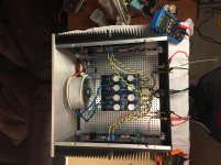
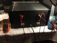
After that experience, I was even more apprehensive about testing my power supply on the bench. I used temporary mechanical connections in some places that were never meant to stay (bare wires wrapped), but I felt comfortable that the temporary wiring was OK (after reviewing it and doing continuity checks at least 4 times). I hooked up my DMMs to read the V+ and V- voltages; plugged the power supply into the dim bulb tester (29W actual) bulb, made sure for the 10th time that the switch on the tester was off; and plugged the tester into the mains outlet. I stepped back… got the camera… and flipped the switch. A quick hit of light caught me off guard, and then the bulb dimmed to off. Beautifully lit LEDs on both sides, and beautifully matching voltages of + 25.7 and -25.7. WOO HOO!
This is seriously thrilling stuff for a noob.
Here are a few pics. I would definitely pick a more suitable place next time. I wasn’t sure what could possibly short together across the chassis, so I left everything on cardboard and separated the transformer from the chassis with cardboard.


If anyone looks at the pics and wonders how I lived through it – please throw out some tips. As careful as I try to be, I’m sure I missed something that made people wonder why I haven’t been removed from the gene pool yet.
Next up – Assemble the chassis with the potentially permanent layout locations and wiring. Add and test each amp channel and set the DC offset. Then - sweet, sweet music.
------------------------
I had my first moments of serious anxiety and basic troubleshooting (because I was too embarrassed to ask), and it had nothing to do with the amplifier itself.
I built my dim bulb tester per the model and schematic on antiqueradio.org. I wanted to verify everything was good before actually plugging in my power supply… So, I plugged it into the wall with only the bulb… paused… took a deep breath, and threw the switch. POP! Goes the circuit breaker. WHAT!?
I should have run continuity checks before plugging it in! I would have known instantly not to plug it in. I had a dead short between the hot and neutral prongs on my plug. It took me forever to figure it out. I (thought I had) wired everything per the diagram. I checked and quadruple checked before plugging it into mains. I was getting a bit upset. I did a quick search for “wiring SPST switch to single outlet”. There it was… in a nice picture (vs. a schematic). I didn’t remove the tab connecting the outlets on the neutral side. DOH! Live and learn. Don’t be as noobish as I.
I chewed a few antacids then fixed it. It took me 3 hours for what should be a 20 minute build. If I had built one like Jim’s (@6l6). I would have probably built it correctly the first try. If I had it to do over again, that’s the route I’d have chosen.
After that experience, I was even more apprehensive about testing my power supply on the bench. I used temporary mechanical connections in some places that were never meant to stay (bare wires wrapped), but I felt comfortable that the temporary wiring was OK (after reviewing it and doing continuity checks at least 4 times). I hooked up my DMMs to read the V+ and V- voltages; plugged the power supply into the dim bulb tester (29W actual) bulb, made sure for the 10th time that the switch on the tester was off; and plugged the tester into the mains outlet. I stepped back… got the camera… and flipped the switch. A quick hit of light caught me off guard, and then the bulb dimmed to off. Beautifully lit LEDs on both sides, and beautifully matching voltages of + 25.7 and -25.7. WOO HOO!
This is seriously thrilling stuff for a noob.
Here are a few pics. I would definitely pick a more suitable place next time. I wasn’t sure what could possibly short together across the chassis, so I left everything on cardboard and separated the transformer from the chassis with cardboard.
If anyone looks at the pics and wonders how I lived through it – please throw out some tips. As careful as I try to be, I’m sure I missed something that made people wonder why I haven’t been removed from the gene pool yet.
Next up – Assemble the chassis with the potentially permanent layout locations and wiring. Add and test each amp channel and set the DC offset. Then - sweet, sweet music.
Last edited:
The final steps toward completion of my first First Watt build was both incredibly frustrating and filled with joy.
First, the frustration – I cannot stand the Dissipante chassis. Period. Full Stop. I’ll give it one compliment. Because of its fully separable panels on all sides, it allows freedom to assemble on the inner base and then assemble the case around it.
To be fair, I may not have assembled it properly (plenty of left over screws). However, the lack of instructions is unconscionable. It is darn near impossible to align the panels without screwing and unscrewing…. Over and over…. Tugging… pulling… Lastly – THERE ARE NO HOLES DRILLED FOR THE FEET. So, once I finally got the thing all put together, I noticed that I’d not only have to take the bottom off again, but drill holes for the feet (which have bolts built in that look far too short, but we’ll see). 
 /rant
/rant
Onto the joy!
– I am very pleased with the overall layout. Yep, I was “inspired” by many of the people here.
– All dim bulb tests went off without a hitch. Left channel and right channels checked separately and together with no magic smoke! I’m still a bit foggy on the entire concept of the dim bulb tests, so I followed the advice in the dim bulb thread and progressed through 4 bulbs from about a ~26W bulb up to ~76W. My higher wattage bulbs did not arrive in time. I said to heck with it and pushed on.
– I dimwittedly tried to set the DC offset the first time with the dim bulb tester in-line. Oops. Then I forgot to short the inputs, oops again. No big deal though. I realized both things fairly quickly by re-reading the process.
– I did a quick offset adjustment after initial power up. I checked it at 20mins, and then let it cook for about an hour and a half. Heatsinks got up to ~47C in the hottest spots. It seems to be questionable as to whether I need to put a dummy load across the speaker terminals to do the final offset adjustment. I have the resistors, but I decided to go with the mighty Zen Mod’s recommendation that it’s not needed. Offset was zeroed to the range of the DMM after cooking.
– I have not checked the bias since it’s autobiasing.
I hooked up some speakers and a test rig – MUSIC! Sweet, sweet music.
I’ve only noticed two very small things to correct and/or live with.
- I get a wee spark in the back panel when I flip the switch. I’ll check the cap. I noticed in my picture it looks like it’s bent from its original location.
- My toroid physically vibrates (seemingly) randomly. When I touch it, it stops. Weird…
Here are a few shots. My plan is to put up a consolidated / long post or some other way to post all the resources I used throughout the build.
I can’t thank the DIYAudio community enough for the support. One more HUGE thank you to @Nelson Pass, @6L6 aka Jim, and @Mark Johnson. There’s also a large number of folks that provided both individual guidance and those from whom I stole their posts and experience shamelessly. They're too numerous to name, but THANKS!
For now, more music!
First, the frustration – I cannot stand the Dissipante chassis. Period. Full Stop. I’ll give it one compliment. Because of its fully separable panels on all sides, it allows freedom to assemble on the inner base and then assemble the case around it.
To be fair, I may not have assembled it properly (plenty of left over screws). However, the lack of instructions is unconscionable. It is darn near impossible to align the panels without screwing and unscrewing…. Over and over…. Tugging… pulling… Lastly – THERE ARE NO HOLES DRILLED FOR THE FEET. So, once I finally got the thing all put together, I noticed that I’d not only have to take the bottom off again, but drill holes for the feet (which have bolts built in that look far too short, but we’ll see).
/rantOnto the joy!
– I am very pleased with the overall layout. Yep, I was “inspired” by many of the people here.
– All dim bulb tests went off without a hitch. Left channel and right channels checked separately and together with no magic smoke! I’m still a bit foggy on the entire concept of the dim bulb tests, so I followed the advice in the dim bulb thread and progressed through 4 bulbs from about a ~26W bulb up to ~76W. My higher wattage bulbs did not arrive in time. I said to heck with it and pushed on.
– I dimwittedly tried to set the DC offset the first time with the dim bulb tester in-line. Oops. Then I forgot to short the inputs, oops again. No big deal though. I realized both things fairly quickly by re-reading the process.
– I did a quick offset adjustment after initial power up. I checked it at 20mins, and then let it cook for about an hour and a half. Heatsinks got up to ~47C in the hottest spots. It seems to be questionable as to whether I need to put a dummy load across the speaker terminals to do the final offset adjustment. I have the resistors, but I decided to go with the mighty Zen Mod’s recommendation that it’s not needed. Offset was zeroed to the range of the DMM after cooking.
– I have not checked the bias since it’s autobiasing.
I hooked up some speakers and a test rig – MUSIC! Sweet, sweet music.
I’ve only noticed two very small things to correct and/or live with.
- I get a wee spark in the back panel when I flip the switch. I’ll check the cap. I noticed in my picture it looks like it’s bent from its original location.
- My toroid physically vibrates (seemingly) randomly. When I touch it, it stops. Weird…
Here are a few shots. My plan is to put up a consolidated / long post or some other way to post all the resources I used throughout the build.
I can’t thank the DIYAudio community enough for the support. One more HUGE thank you to @Nelson Pass, @6L6 aka Jim, and @Mark Johnson. There’s also a large number of folks that provided both individual guidance and those from whom I stole their posts and experience shamelessly. They're too numerous to name, but THANKS!
For now, more music!
Attachments
Congratulation with the build!
There is an "exploded" drawing on how to assemble the chassis. I think when you learn how to deal with the tricky parts of the assembly you get used to it. One of the tricks is to get the side panels far enough from each other so top and bottom can be mounted (alignment of screw holes).
Do you have any hum problems? …..sensitive speakers?
@cubicincher and @MEPER - Thank You!
@MEPER - Yes, I mentioned the drawing previously... but... that drawing is not only inaccurate, but useless visually. It offers no better information about the assembly than raw intuition would provide. I could not discern hardware types, etc. The top and bottom panels were definitely one issue. When you secure the inner base to the rails attached to the heatsinks, it can pull inward. Thus they need to be slightly loose before putting on the bottom panel. But, the screw-heads are recessed on the rails ... ON THE BOTTOM. I managed to solve it by leaving them loose and attaching the base plate offset (only 4 screws attached) to the front - then tighten the inner base, and then to the rear and repeat. That forced the alignment of the rails to fit the panels while still allowing access to the screws to secure the rails to the inner base.
If I were ever to buy one of those chassis again - I'd do it in the following order.
1) Rails to heatsinks
2) Rails to inner base (loose) - do all the assembly and wiring
3) Run initial checks up to and including rough DC offset
4) If wiring is routed under the inner base, secure it. Ensure all standoffs and all mounts to inner base are secure and everything is in final locations.
5) Drill holes in base plate for feet
6) Offset the base plate to the front or rear and secure with 4 screws. Tighten exposed inner base screws.
7) Remove base plate and offset it the other direction (it was necessary) - tighten remaining 2 screws to secure the inner base.
8) Put on feet
9) Secure base plate.
10) Secure the top plate (offset) with 4 screws - install the back plate
11) Secure the top plate (offset) with 4 screws - install the front plate
12) Bake and run final DC Offset
13) Secure top plate
It's all irrelevant now - I love it! It may be like the pain of child birth. No matter how bad it is, you love the child and would do it again. Don't tell my wife I said that!
I haven't hooked it up to any sensitive speakers yet, but I can put my ear directly up to my test speakers and not hear a thing, literally silent with no input signal and volume on the pre-amp (test) cranked up to what would be ear-splitting levels. There is a bit of hiss at crazy input voltages that I'd never get to, but I'd assume that's from the pre-amp and not the amp. I saw some posts re: actually measuring the noise with a DMM / AC Voltage and trying to ensure it was under a certain threshold, but I think I’m doing it wrong. I’ll get it moved to the main speakers (~98dB / 1W / 1m) and report back.
Currently, the only "hum" is from the toroid physically vibrating and resonating with the chassis. I left it on to cook, and it seems to have quit over night, but I have not “solved” that yet. The toroid is getting up to about 65C. I don’t know if that’s normal, so I’m researching. The mount I'm using has rubber pads to secure the toroid to the mount, but there is no "anti-vibration" pad between the mount and the inner base. If I can't get rid of the vibration, or if that's "normal" - I'll rig up a pad to at lessen the transfer of the hum to the chassis.
Right now, it all seems good.
PS - I solved the little spark at the AC switch at turn on. The capacitor across the mains got bent during chassis assembly and was touching the toroid. I bent it back, and all seems to be good.
Thanks!
- Home
- Amplifiers
- Pass Labs
- A Noob's First First Watt - M2x