Hi there,
The subject of visualizing the mains waveform on an oscilloscope has always generated a lot of controversy, bad advice, and as a result topic closures by the moderation for obvious safety reasons.
Here is a typical recent example:
http://www.diyaudio.com/forums/equipment-tools/284393-how-measure-120v-mains-oscilloscope.html
I propose a different approach, simple and easy, yet 100% safe provided you follow strictly the guidelines, and use a bit of common sense.
I am pretty sure my approach will cause an outcry, because it is a non-isolated (sort of, more on that later) circuit connected to both the mains and the oscilloscope, but sensible people will very quickly realize that this method is indeed extremely safe, more so than any alternative available to DIY people, including transformers.
It is also quite faithful, at least for relatively low frequency signals.
The circuit couldn't be simpler:

It is just a textbook difference amplifier.
The smart bit is that no "ground" or "common" terminal is used at the input.
How can it work, and why is it "smart"?
-It works, because the common mode voltage will either be imposed by the source (this will be the case with mains-connected circuits), or generated by the circuit itself (for isolated sources like inverters or transformers).
-It is smart, because it eliminates all of the usual safety issues encountered with other solutions: there will be a small leakage current, but perfectly controlled, deterministic and completely safe.
There is no need to change anything to the earthing arrangements of the DUT or the oscilloscope, or to use an isolation transformer: everything works simply and transparently.
The leakage current is determined by the value of the input resistors, 230µA maximum here.
This value is perfectly safe, and will have no impact on a human or a GFI, even a sensitive one.
Note that the grounds of the supply and of the oscilloscope still need to be connected to a protective earth, in case something fails.
The principle also allows for safe handling: even when the circuit is left floating, with the power and the output disconnected, you can safely touch one of the terminals while the other is plugged into the hot side of the mains: the maximum current you will experience in this case is 58µA: completely safe.
Now, it's time for ....
This circuit is completely safe if built properly and using proper components, but even it can be deadly if you are sloppy, negligent, or if you try to save a few pence on the wrong things.
Mainly two things matter:
Clearances:
The distance between an input terminal and the opamp side must be greater than 20mm.
The distance between the two input terminals has to exceed 10mm.
The clearance area must be free of any conductive element: copper track, pad, or any foreign object.
Components:
The input resistors must be of a high voltage type (>1250V breakdown voltage) and must be composed of at least two elements.
Do not compromise on the quality!
Risking life and injury in order to save a few cents is a very bad calculation, and you have to choose a reliable seller: if you find HV resistors on Ebay, they are most likely ordinary carbon or metal film types in disguise.
Use known and reliable outlets: RS, Farnell, Mouser to name a few.
Choose a known and reliable manufacturer: Vishay, Yageo, Philips, etc.
Here is the datasheet of the resistors I used:
http://www.farnell.com/datasheets/1511320.pdf
Other acceptable models include VR25 from Philips or Vishay for example
The circuit can be built on a regular PCB, or on a perfboard as in my example. In this case, either chose a "naked" one (no pads), or remove the pads surrounding the input resistors:


The finished circuit must be housed in an insulating case: I have used a plastic (PP) drug container:

For additional safety, I have placed the probe inside a heatshrinking tube:

Any other similar option is acceptable, but do not use anything containing metal.
There is no "common" connection in sight, but that's on purpose: such a connection is not only superfluous, but it could lead to to dangerous mistakes: with only two input leads, the room for errors and mistakes is seriously curtailed (though I wouldn't swear it is idiot-proof: that's a dangerous thing to state).
To be continued, and in the meantime, be careful!
The subject of visualizing the mains waveform on an oscilloscope has always generated a lot of controversy, bad advice, and as a result topic closures by the moderation for obvious safety reasons.
Here is a typical recent example:
http://www.diyaudio.com/forums/equipment-tools/284393-how-measure-120v-mains-oscilloscope.html
I propose a different approach, simple and easy, yet 100% safe provided you follow strictly the guidelines, and use a bit of common sense.
I am pretty sure my approach will cause an outcry, because it is a non-isolated (sort of, more on that later) circuit connected to both the mains and the oscilloscope, but sensible people will very quickly realize that this method is indeed extremely safe, more so than any alternative available to DIY people, including transformers.
It is also quite faithful, at least for relatively low frequency signals.
The circuit couldn't be simpler:
It is just a textbook difference amplifier.
The smart bit is that no "ground" or "common" terminal is used at the input.
How can it work, and why is it "smart"?
-It works, because the common mode voltage will either be imposed by the source (this will be the case with mains-connected circuits), or generated by the circuit itself (for isolated sources like inverters or transformers).
-It is smart, because it eliminates all of the usual safety issues encountered with other solutions: there will be a small leakage current, but perfectly controlled, deterministic and completely safe.
There is no need to change anything to the earthing arrangements of the DUT or the oscilloscope, or to use an isolation transformer: everything works simply and transparently.
The leakage current is determined by the value of the input resistors, 230µA maximum here.
This value is perfectly safe, and will have no impact on a human or a GFI, even a sensitive one.
Note that the grounds of the supply and of the oscilloscope still need to be connected to a protective earth, in case something fails.
The principle also allows for safe handling: even when the circuit is left floating, with the power and the output disconnected, you can safely touch one of the terminals while the other is plugged into the hot side of the mains: the maximum current you will experience in this case is 58µA: completely safe.
Now, it's time for ....
WARNINGS!
This circuit is completely safe if built properly and using proper components, but even it can be deadly if you are sloppy, negligent, or if you try to save a few pence on the wrong things.
Mainly two things matter:
- The construction, in particular the distances and clearances.
- The quality of the input resistors: all of the safety relies on them, and if you use the wrong type, it could be seriously compromised
Clearances:
The distance between an input terminal and the opamp side must be greater than 20mm.
The distance between the two input terminals has to exceed 10mm.
The clearance area must be free of any conductive element: copper track, pad, or any foreign object.
Components:
The input resistors must be of a high voltage type (>1250V breakdown voltage) and must be composed of at least two elements.
Do not compromise on the quality!
Risking life and injury in order to save a few cents is a very bad calculation, and you have to choose a reliable seller: if you find HV resistors on Ebay, they are most likely ordinary carbon or metal film types in disguise.
Use known and reliable outlets: RS, Farnell, Mouser to name a few.
Choose a known and reliable manufacturer: Vishay, Yageo, Philips, etc.
Here is the datasheet of the resistors I used:
http://www.farnell.com/datasheets/1511320.pdf
Other acceptable models include VR25 from Philips or Vishay for example
The circuit can be built on a regular PCB, or on a perfboard as in my example. In this case, either chose a "naked" one (no pads), or remove the pads surrounding the input resistors:
The finished circuit must be housed in an insulating case: I have used a plastic (PP) drug container:
For additional safety, I have placed the probe inside a heatshrinking tube:
Any other similar option is acceptable, but do not use anything containing metal.
There is no "common" connection in sight, but that's on purpose: such a connection is not only superfluous, but it could lead to to dangerous mistakes: with only two input leads, the room for errors and mistakes is seriously curtailed (though I wouldn't swear it is idiot-proof: that's a dangerous thing to state).
To be continued, and in the meantime, be careful!
Last edited:
Well, you could, but in a limited measure: I will come back on that with more details later, but I can already say that this is one of of the performance limitation of this scheme: if you try to amplify a small differential voltage riding on a much larger common-mode one, you will be confronted with CMRR issues, just like any audio bal-to-unbal electronic converter or instrumentation amp.Thank you.
Can this be used as a scope differential input for amplifier testing where the two "ends" are both at an elevated voltage?
In my prototype, I hand-picked the resistors to have a better than 0.05% ratio matching between the two dividers, but even that wouldn't be sufficient to measure correctly the voltages across the emitter resistors of an amplifier delivering its full 150Vpp swing.
If the voltage to be measured is somewhat larger, or if you know what to look for (for example measuring a small AC voltage affected by a large DC offset), and your resistors are accurately matched, it is possible, but the main purpose of this probe is to measure large differential voltages whilst tolerating large common-mode ones.
With the values indicated, the CM voltage could reach almost +/-1kV, which is clearly overkill for audio applications. You could use a smaller ratio than 1/100: this will improve SNR issues, but not the CMRR ones.
Matching the resistors to a higher degree is possible, but with ordinary opamps, this will only help the LF rejection, not the HF one
Yes you can, it will rid the output of any DC component, including the common-mode one, which is likely to be the most problematicCan one add DC blocking capacitors to the inputs? Would that bring any advantages?
")
Before going further, here are some useful reminders:
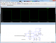
Now let's talk about performance.
Here is the 10KHz squarewave response:

It is somewhat rounded, but perfectly recognizable. The measured -3dB bandwidth is 1.5MHz, with a LF356 as opamp and the crude compensation shown on the schematic.
The behavior is almost identical with a LF411 or a TLO71.
This means that the bandwidth is primarily limited by the compensation, not the opamp itself, and before upgrading to a faster type, the compensation should be refined.
The compensation relies on the self-capacitance of the input resistors; this capacitance is not only very small, but it is also "impure": because of the distributed coupling to the opposite side, the PCB and the ambient space, it cannot be compensated by pure, lumped capacitors.
If you want to exploit the full bandwidth of the opamp, you would need a number of RC networks instead.
I didn't take the time to tweak this aspect, because it was not needed for the application in mind, but it is probably possible to gain one order of magnitude with some patience.
On my prototype, the LF CMRR is about 60dB. It begins to degrade as of ~25KHz.
The LF figure can be improved with a tighter resistor matching, but it will be difficult to improve the HF performance: the degradation is caused not only by the opamp itself, but also by the layout: it is very "open" for safety reasons and the insulating case makes it sensitive to proximity or hand effects.
Reconciling shielding and safety would be very difficult at an amateur level, and shouldn't be attempted.
These performances mean it would also be usable for basic troubleshooting of ordinary SMPS's: it is sufficient to assess the presence of a signal and appreciate its global outlook, but finer details like transition times will be completely lost.
For development work, it would be useless.
If great DC accuracy is required, the opamp can be equipped with an offset trimmer.
The resistors values and ratio's can be modified to suit the exact application: I have chosen values as low as possible whilst keeping the worst-case leakage < the 250µA limit.
Lower values are in principle preferable, because they are more stable, and make the probe less sensitive to electrostatic effects. If required, the value can be made much larger, like "standard" 10Meg for instance
The resistors I used have a theoretical limit of 3.5kV, which means 7kV for the pair, but the 1Meg value mean they are in fact dissipation-limited to a total of 1kV, which matches nicely the common-mode limit with 12V supplies.
Note that the theoretical 7kV are not useless: they still apply for pulses, and that matters very much for safety.
More than a pair of resistors can be used on each side, but not less, for safety/reliability reasons.
The current consumption is ridiculously low: ~3mA on each supply rail, meaning the supply can be simplified to the extreme: a 1~3VA transformer, a pair of diodes for half-wave rectification, a pair of 220µF for filtering and 78L12/79L12. 12V zeners would also be perfectly sufficient here. Do not forget to earth the PSU.
This probe would also be perfect for work on tube power amplifiers: its limitations would not be problematic there.
For preamp work, the impedance is too low, and 10Meg or higher should be used.
I also include the sim file:
- Do not use the probe in a "half-finished" state (ie naked PCB with flying leads)
- Make sure it is properly encased in a completely hermetic, insulating case
- Before you definitively close the case, make sure no foreign object has accidentally found its way inside: solder splash, cut wire, washer, etc, ....
- Secure the input leads properly, or block them so that they cannot be ripped off; alternatively, use female receptacles
- Before you connect or move the inputs, be sure to always power off the DUT. Never make a manipulation on a live circuit.
- If you intend to use this probe in a "difficult" environment (humidity, dust, grease, dirt, ...) apply a silicone-based conformal coating to the board
Now let's talk about performance.
Here is the 10KHz squarewave response:
It is somewhat rounded, but perfectly recognizable. The measured -3dB bandwidth is 1.5MHz, with a LF356 as opamp and the crude compensation shown on the schematic.
The behavior is almost identical with a LF411 or a TLO71.
This means that the bandwidth is primarily limited by the compensation, not the opamp itself, and before upgrading to a faster type, the compensation should be refined.
The compensation relies on the self-capacitance of the input resistors; this capacitance is not only very small, but it is also "impure": because of the distributed coupling to the opposite side, the PCB and the ambient space, it cannot be compensated by pure, lumped capacitors.
If you want to exploit the full bandwidth of the opamp, you would need a number of RC networks instead.
I didn't take the time to tweak this aspect, because it was not needed for the application in mind, but it is probably possible to gain one order of magnitude with some patience.
On my prototype, the LF CMRR is about 60dB. It begins to degrade as of ~25KHz.
The LF figure can be improved with a tighter resistor matching, but it will be difficult to improve the HF performance: the degradation is caused not only by the opamp itself, but also by the layout: it is very "open" for safety reasons and the insulating case makes it sensitive to proximity or hand effects.
Reconciling shielding and safety would be very difficult at an amateur level, and shouldn't be attempted.
These performances mean it would also be usable for basic troubleshooting of ordinary SMPS's: it is sufficient to assess the presence of a signal and appreciate its global outlook, but finer details like transition times will be completely lost.
For development work, it would be useless.
If great DC accuracy is required, the opamp can be equipped with an offset trimmer.
The resistors values and ratio's can be modified to suit the exact application: I have chosen values as low as possible whilst keeping the worst-case leakage < the 250µA limit.
Lower values are in principle preferable, because they are more stable, and make the probe less sensitive to electrostatic effects. If required, the value can be made much larger, like "standard" 10Meg for instance
The resistors I used have a theoretical limit of 3.5kV, which means 7kV for the pair, but the 1Meg value mean they are in fact dissipation-limited to a total of 1kV, which matches nicely the common-mode limit with 12V supplies.
Note that the theoretical 7kV are not useless: they still apply for pulses, and that matters very much for safety.
More than a pair of resistors can be used on each side, but not less, for safety/reliability reasons.
The current consumption is ridiculously low: ~3mA on each supply rail, meaning the supply can be simplified to the extreme: a 1~3VA transformer, a pair of diodes for half-wave rectification, a pair of 220µF for filtering and 78L12/79L12. 12V zeners would also be perfectly sufficient here. Do not forget to earth the PSU.
This probe would also be perfect for work on tube power amplifiers: its limitations would not be problematic there.
For preamp work, the impedance is too low, and 10Meg or higher should be used.
I also include the sim file:
Attachments
Last edited:
- Status
- This old topic is closed. If you want to reopen this topic, contact a moderator using the "Report Post" button.