I do too. In fact, I'm working on my masters in it! LOL( I actually have a degree of confusion
Mister Audio,You're both onto what I was trying to say. I have been using my own terms/words to explain all I have read & watched.
( I actually have a degree of confusion between modes and nodes, although related )
The one thing I have noticed is a very strong consensus that a single exciter should not be placed dead center.
It would be good if someone else could 'jump in' and expand upon this topic of exciter location.
PS.
I would never use twin exciters out of phase.
Concerning "nodes and modes" perhaps I can try to explain....
Panels, like all structures, have a set of frequencies at which they "prefer" to vibrate. These are called natural frequencies, resonant frequencies, or even eigen-frequencies. And the set of natural frequencies of any panel depends on the material properties of the panel (primarily its elastic modulus and density), as well as its shape and dimensions (length, width, thickness), and its supports (are the edges free, or hingelike, or clamped?)
At each of these natural frequencies, the panel has a different characteristic "shape". Each of those shapes is a "mode". Here is an example of some of the shapes, or modes, for a typical plate:
Or, for an animation, see here:
https://resource.isvr.soton.ac.uk/spcg/tutorial/tutorial/Tutorial_files/Web-standing-membrane.htm
When a plate is vibrating at the natural frequency associated with a particular mode shape, there are locations on the plate where the vibration amplitude is a maximum (i.e at the centers of the red and blue regions in the images above), and these location are called anti-nodes. Also, there are places where the vibration amplitude is zero (i.e at any point along the gray lines in between the red and blue regions), and these are called nodes.
As you can see in the images above. Nodal regions are typically lines, while antinodes are technically points. For example, for mode 2 in the figure, the gray line between the red and blue regions is a "nodal line", while the centerpoints of the red and blue regions are anti-nodal points, or simply anti-nodes.
Concerning the question of exciter location: An exciter will be most effective at "activating/exciting" a particular mode of vibration if it is located near one of the anti-nodes for that particular mode. Conversely, an exciter located along a nodal line for a particular mode of vibration, will not be able to "activate" that mode at all.
The reason that the center is considered to be poor choice of location for a single exciter is because the nodal lines of many of the modes pass directly through the center of the panel. Hence, placing an exciter in the center activates fewer modes of vibration than virtually any other point.
The idea of using the often cited 2/5 position likely stems from the patents of Azima/NXT, who advocated placing the exciter(s) at locations that avoided the antinodal lines as much as possible, to activate as many modes of vibration as possible, and hopefully thereby produce the smoothest frequency response possibe. Interestingly, the NXT patents never actually cited the 2/5 location. Rather, they cited several other location ratios, such as 3/7, 4/9, and 5/13. But all of these are pretty close to 2/5, so I suspect someone just decided 2/5 was probably good enough and that ratio become popularized on you-tube etc.
Likewise, I would probably not use two exciters out of phase on the same panel for any real speaker. But I actually do build test speakers with variations like that all the time, just to see what happens and to test my understanding of how these things work. That's where the real fun is!
I hope this helps.
Eric
Yes, but...The impedance peak without a brace actually reduces heat (and power consumption) at very low frequencies.
+ @Veleric : Eric, your impedance measurements are steps to a better model of the DML behavior. Thank you for publishing it.
So to come back to what happens in free magnet conditions (no brace/spine) : as it was pointed in #11100 (@Eucyblues99 ), it is a coupled mass system. When the resonance of the magnet occurs (about 30Hz in the measurement), it limits the current in the system so the power in the voice coil and in consequence the force applied to the panel.
The problem is when this happens, the displacement is important leading to request to the exciter to work in an unwanted area of its stroke and then inducing distortion or compression in higher frequencies.
You will find in the attached file how the standard modelling of a loudspeaker can be applied to this first resonance to get an equivalent electrical circuit. Sorry, I haven't found an "easy to read" source to explain this... The source for today was in an excel file from M Linkwitz
In a certain way, letting the magnet free is the same as adding a RLC notch filter in series with the exciter... in worse speaking about the possible non linearity.
The next step should be to analyze what happens depending where this resonance is compare to the 1st mode of the panel. In the example you posted Eric, the magnet resonance is much below the 1st mode (even if it is not easy to say where is the 1st mode...). Is there a risk depending of the exciter/panel material and dimensions this resonance interfere in the bandwidth? The answer should be possible going further in the topic.
Waiting for that... it is one additional point in favor of a spine?
In the next steps I see from the impedance measurement is the evaluation of the damping as you suggest Eric. It is time to come back to modelling... when I will have fully re-install the needed software on my (new) computer.
Christian
Attachments
Hi LeobIf the fundamental mode is very strong you will get a narrow response, so it makes sense trying to tame that.
Can you please explain the logic behind this statement. How does a strong bass response restrict the frequency range response?
Thanks
Eucy
In addition to my previous post, a LTspice simulation (now re-installed on my computer!) showing the simplified model above fits pretty ok to the impedance measurement (model for 1st resonance and HF... even if L2 is a bit small here).
In the simulation as the AC current source is 1A, the voltage is equivalent to the impedance (1V <> 1Ohm)

And here the filter effect (means the equivalent attenuation). Pretty steep (-3dB at 40Hz)

In the simulation as the AC current source is 1A, the voltage is equivalent to the impedance (1V <> 1Ohm)
And here the filter effect (means the equivalent attenuation). Pretty steep (-3dB at 40Hz)
Hi Eucy,Hi Leob
Can you please explain the logic behind this statement. How does a strong bass response restrict the frequency range response?
Thanks
Eucy
I probably misunderstand the question or what is unclear....I think we all agree that high sensitivity in a narrow band means an overall more narrow response, and that distributing modes is how you smoothen the FR of a DML speaker?
From FR perspective it doesn't matter if a part of the spectrum is stronger or the rest is weaker, it is still a bandpass response if you have a narrow part of the spectrum that is louder. And that is what you get with a DML that where higher order modes are not strong enough.
I guess you might mean that you could try to improve the other modes instead of taming the dominant modes? In practice I think that happens when you select a good material and dimensions. For example, a more "dead" material, like the thermoplastics I experimented with, will fail to excite the higher order modes, and then indeed the issue is not the strong first couple of modes, but rather the lack of higher order modes.
On the other hand, when you have found a material and dimensions that gives a good response, I'm not sure how you would improve weak modes, but you can still tame strong modes with for example suspension and weights to further improve FR, but then at the cost of some sensitivity.
You might think the braced exciter would give better base response. I did too until I tried it. But the several times I have compared the same speaker with and without a brace, there was no increase (or decrease) of any significance in the base response.But instinctively I would say that bracing will give you a bit better bass response, and at 35hz you will get more acoustic power, but also use more electric power with the lower impedance.
For example, the results below include the frequency responses I obtained with the same speaker assembly, with and without the brace, along with the impedance results I shared earlier. The dashed lines are without the brace, and the solid lines are with the brace. I have tried this same test at least a half dozen times with different speakers but the same result, that is, no significant effect on frequency response.
In the example you posted Eric, the magnet resonance is much below the 1st mode (even if it is not easy to say where is the 1st mode...).
Indeed that is a fair point. In fact, the 1st mode of this panel is at 100 Hz (confirmed by tap testing and the impedence curves). It's possible that the results would be different if the panel had a lower first modal frequency.
Eric
Really good & interesting information above !
But there is something I need to question >
If we had a massive impedance peak with a midrange or tweeter, we would want to
tame (cancel) it using an electrical notch filter, so a crossover design could work properly.
But what I don't understand is why we would use an electrical notch filter @ 30Hz ?
To my mind, we would only increase 30Hz power consumption, without any real sonic improvement.
Could someone explain further as to why 'taming this 30Hz peak' makes things better ?
I concur entirely 👍👍You might think the braced exciter would give better base response. I did too until I tried it. But the several times I have compared the same speaker with and without a brace, there was no increase (or decrease) of any significance in the base response
I would have thought the +5dB difference around 70Hz would be audible. It is a very important range for bass reproduction, and I'm a bit surprised if it is not a noticeable difference, but you probably would need to do AB testing to spot it. And when it comes to power applications it is certainly significant. 5dB at 70Hz is the same difference in power as 11dB at 140Hz or 17dB at 280Hz.You might think the braced exciter would give better base response. I did too until I tried it. But the several times I have compared the same speaker with and without a brace, there was no increase (or decrease) of any significance in the base response.
For example, the results below include the frequency responses I obtained with the same speaker assembly, with and without the brace, along with the impedance results I shared earlier. The dashed lines are without the brace, and the solid lines are with the brace. I have tried this same test at least a half dozen times with different speakers but the same result, that is, no significant effect on frequency response.
View attachment 1240446
Overall the bass response seems stronger in the unbraced, and response in the braced version looks very similar except that it is pushed up a few Hz below the first mode of the plate, so certainly confirms that I was wrong in my speculation.
Very interesting, but haven't got a clue about the physics behind it

The bracing obviously acts to impede the exciter movement at FS, and I guess that energy has to go into the plate in the end somehow, at least it cannot all turn into heat, but cannot understand how that would push the response upwards like that.
I think what I can take away from your excellent data is that since bracing will lower the overall SPL slightly, either more heat is generated or less power is consumed. I guess the former is more likely.
Of course there is different kinds of bracing, and I been leaning towards having it as unrestrictive as possible, and your measurements seems to indicate that bracing doesn't really serve any purpose other than to hold the exciter in place.
I initially had no bracing for the exciters on plates since I was getting better results without. The problem is that with time and heat exciters will start to sag and distort. So for me the goal has not been to hold the exciter in place against the force direction, but rather to support it enough vertically to avoid sagging.
In the latest design of my bracing plates I print them in dual material with TPU (soft rubber-like thermoplastic) around the screw mounts. I should be able to put together a test plate with the new bracing this weekend, and I hope the softer suspension in the bracing will mean that they are still fixed enough vertically, while still allowing the exciter to act a little bit more like it was unbraced.
Leob, buried somewhere in these 562 pages, are references and details relating to exciter suspension methods (as distinct from bracing) involving modified plastic clothes hangers (call this type 1), and modified zip ties (type 2), which I use and find work admirably.
Not sure if I can find them though...😵💫
Eucy
Not sure if I can find them though...😵💫
Eucy
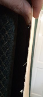
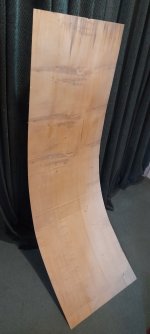
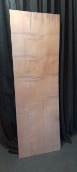
While I was getting some plumbing supplies in wickes diy store, I noticed this sheet of 1mm 6x4ft scrap of ply🤔
I could not stop myself from asking if I could have it.
As you can see from the three pictures it is exceedingly flexible.
I was hoping it was a single ply so that I could test different flexibilities in different directions.
But when I got home I found it was a 2ply.🙄
My wife was very happy to see this suddenly turn up in my front room, overjoyed in fact🤥🤣
I will have to find somewhere to hide this, until I get around to testing.
Which will probably be some time, as I have a lot on my plate at the moment .
The idea was to make small panels , time will tell.
Steve.
Attachments
Hello ajh,
Could you evaluate its density and if you have the possibility, post a frequency response (the question I have in mind is how it behaves in HF)?
Thank you
Christian
Many issues popped up and have slowed my progress.
I did make some panels from 2.7mm Meranti plywood 2'x3' with rounded corners. 1 40W Dayton exciter per panel placed off center. The weight of the plywood is approx 8.25 oz per sq ft or 2518 grams per square meter.
I do not yet have anyway to measure FR. My subjective evaluation was that it was a mixed bag. I thought it was stellar on vocals, guitar, cello. It did seem to be missing the high end audibly. Moreover it seemed overly damped. It seemed very inefficient - and was compared to other materials I tried. I think the biggest challenge was in getting them to blend with the subwoofer. Just too much difference in efficiency I think.
I also tried some 1/2 inch Foamular. It achieved much more volume with the same amp and had more high end, but seemed to have a real nasal quality which I guess was a resonance.
The best so far has been double wall polycarbonate. It seems to be much better. I have 2 sets now.
Set 1 is in my wife's sewing room mated to a sub I picked up at a thrift store for $10. The room is about 11'x 13' and the polycarbonate panels are 2'x 4' are hanging at one end of the room - kinda angled from the corners. ~7 inches off the wall at the close end and about 12" off the wall at the corner. Both sub and panels are powered by a Fosi amp.
They sound great and very dynamic. They get very loud in this room and integrate really well with the subwoofer. No complaints. Snare drums sound especially good. There is a certain quality to a live snare drum that I have never really heard reproduced by a speaker. I didn't realize that until I heard it on these panels. Interestingly, you can hear them ring for an instant when you turn off the music. Probably, not a great thing but oh well.
Set 2 is in the living room. They are powered by an Arylic B50 and I picked up a Cerwin Vega LW12 powered sub to cover the low end. This is the system that I tested the plywood and Foamular on. Then I decided to make another set of polycarbonate panels for now. They are about 7-8" off the wall and they hang with elastic cord from my wife's sewing stash. These were painted with spray paint to match the walls. Not sure if it is the room or the spray paint or both, but they do not seem to ring as much as set 1 and they do not seem quite as loud or efficient. They do a much better job of blending with the sub than the plywood.
The polycarbonate panels seems to do everything well, but I do miss the plywood for vocals, acoustic instruments. Something about it is kinda addictive. Perhaps with more experimentation, the issues with the plywood could be overcome.
Below are the results of a second test that I just performed, comparing SPL and impedance curves with and without a brace supporting the exciter. In the new test, I used a panel with a much lower fundamental frequency (about 43 Hz) than the panel in the previous test (about 100 Hz). The panel in the new tests is a 48"x18" panel of 14 mm thick XPS.
The dashed lines are the results with no brace, and the solid lines are the results with the brace. As in the previous test, the addition of the brace eliminates the impedance peak associated with exciter's mass and spider (at about 25 Hz in this case). Interestingly, the addition of the braces reduces height of the first several panel resonances as well.
Concerning the SPL, there appears to be some increase in bass output without the brace, particularly below about 60 Hz. In the previous test there was a similar (but much smaller) effect.
For me, evidence is building that the addition of brace does not increase bass output, but rather may actually decrease it. That said, I wouldn't consider the elimination of the brace to be a meaningful improvement to this panel, as to me this panel is really only "useable" above about 200 Hz (if at all).

These results demonstrate another thing that I've observed fairly consistantly (but has nothing to do with the brace). Which is that if I build a panel with a fundamental frequency of about 80 Hz or higher, there is a chance (with the right aspect ratio, right suspension and right exciter placement) that the SPL response can be reasonably flat above the panel's fundamental frequency up to at least 5 kHz (or even 15 kHz). But If I build a panel with a lower fundamental frequency, I inevitably end up with a big gap in the frequency response between the fundamental and about 150 to 200 Hz. So while tuning the panel lower allows significant bass output, it's not what I consider "useful" output, The present panel is a good example of that, with the large dip in output between about 50 and 200 Hz. For this reason I've pretty muched stopped even trying panels like this where the fundamental is below about 80 Hz.
Eric
The dashed lines are the results with no brace, and the solid lines are the results with the brace. As in the previous test, the addition of the brace eliminates the impedance peak associated with exciter's mass and spider (at about 25 Hz in this case). Interestingly, the addition of the braces reduces height of the first several panel resonances as well.
Concerning the SPL, there appears to be some increase in bass output without the brace, particularly below about 60 Hz. In the previous test there was a similar (but much smaller) effect.
For me, evidence is building that the addition of brace does not increase bass output, but rather may actually decrease it. That said, I wouldn't consider the elimination of the brace to be a meaningful improvement to this panel, as to me this panel is really only "useable" above about 200 Hz (if at all).
These results demonstrate another thing that I've observed fairly consistantly (but has nothing to do with the brace). Which is that if I build a panel with a fundamental frequency of about 80 Hz or higher, there is a chance (with the right aspect ratio, right suspension and right exciter placement) that the SPL response can be reasonably flat above the panel's fundamental frequency up to at least 5 kHz (or even 15 kHz). But If I build a panel with a lower fundamental frequency, I inevitably end up with a big gap in the frequency response between the fundamental and about 150 to 200 Hz. So while tuning the panel lower allows significant bass output, it's not what I consider "useful" output, The present panel is a good example of that, with the large dip in output between about 50 and 200 Hz. For this reason I've pretty muched stopped even trying panels like this where the fundamental is below about 80 Hz.
Eric
Something else I've noticed about DML performance (again completely subjective)...Hi aagas.
I totally agree with these comments, I have had these exact experiences.
I used to play around with all sorts of amps wires CD players, you name it.
Now whatever I plug into my panels sounds fantastic.
Even my very cheap surround amp in my living room.
They produce such realistic sounds that I have not worried about cabling, amps and such things.
When instruments and sounds , sound so realistic, what more could you possibly want.
I used to try everything to squeeze just a little more atmosphere and detail.
But since I first heard dml , I have not felt the need to try and make minute changes to equipment , as the sound of dml is like night and day compared to other types of sound producers.
If I ever stop making different panels ,I am sure I will probably start thinking of other ways to improve the sound again.
But the system sounds so good I can't see that happening very soon.
As you say , those things only make minor changes that aren't that important, to me that is 😃
Steve.
In my experience, on conventional (even very high end) equipment, Maria Callas recordings had a shrillness and stridency that (for me) made them difficult to engage. I could only listen to so much of them at a time. Of note, I experienced this somehow separately from the power and emotional impact of the recordings that always had me convinced.
The same recordings on DMLs become velvety - all that harshness gone.
I didn't have the chance to hear her live. Other things drew my attention in those young years of my life. I suspect the DMLs give one a more realistic experience of the original.
My conjecture - DMLs more fully reproduce the complexity of overtones, position, and atmosphere that then integrate that earlier experienced shrillness and stridency into the music. Instead of dominating the recording of the performance it seasons, deepens, and enriches it.
I've had similar experiences with recordings of Ornette Coleman.
DMLs just make one re-experience all the music one thinks they know.
Oh I'm sure she was as thrilled as my wife would have been!I was hoping it was a single ply so that I could test different flexibilities in different directions.
But when I got home I found it was a 2ply.🙄
My wife was very happy to see this suddenly turn up in my front room, overjoyed in fact🤥🤣
But are you sure it's not 3-ply? 2-ply would be really unusual, and particularily prone to warping. Except for veneers, I've never hear of it.
Eric
Eric.
I believe this is the centre core of an unfinished scrap 3 ply .
I always thought the centre core was a solid sheet, but am now not so sure ?
It was probably placed over the stacked ply sheets to protect them from damage.
It would have been thrown in the bin after delivery.
Hence they gave it to me free of charge 🤑🤗
I could not resist.
Steve.
- Home
- Loudspeakers
- Full Range
- A Study of DMLs as a Full Range Speaker