Hi Forum,
I decided to make a tube only RIAA phono stage and make a nice over the top PCB for it. The design is a bit based on the Luxman EQ 500 with less bell and whistles, but in basic form the same thing.
A friend of mine wanted to tag along.
We ordered 3 main boards, one to prototype on and we only put components for one channel on.
This would not ruin the end result for if we would have had to cut traces and blow up things.
Luckily the board had only one error (a PNP transistor with Collector and Emitter swapped in the foortprint) in the slow start function of the 12.6V filament supply.
So, the concept is a dual 12AX7 based SRPP stage running on 320V with a passive RIAA in between. No NFB. I made a separate left and right regulator with a bit beefy supply. A custom transformer ordered with 2x 350V CT, 14V for the heaters and relays and 6,3V for the Tube rectifiers.
Used an ECC88 for the output stage running on 250V but two halves in parallel. The ECC88 has a low output impedance and 2 parallel is below 50 Ohm. A Lundahl transformer for the MC input and one to make a balanced output. The output stage is also AC coupled with a floating bias resistor to bias the output tubes (way more predictable and a beefy 16mA class A current trough the combined parallel tubes. I also made a reverse RIAA circuit tweaked it to 0,1% and a channel balance of 0,1dB.
I used 30nF and 10,2nF in the RIAA stage and measured with an Audio Precision. The theoretical values would be 72k and 10,6k for the RIAA resistors.
The 72k is way to high as you need to add the output impedance of the SRPP and the impedance of the coupling capacitor and the result is shown in the attached picture. Distortion was -74dB A weighted dominated by the 50Hz mains and no case yet.
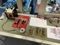
So last weekend my friend and I have been working on the main boards see attached pictures for the result.
Missing a few components, and the metal cooling plate in the middle that you see on the proto will be black anodized next week.
Then we can test again, and work on the housing.
Cheers
Peter
I decided to make a tube only RIAA phono stage and make a nice over the top PCB for it. The design is a bit based on the Luxman EQ 500 with less bell and whistles, but in basic form the same thing.
A friend of mine wanted to tag along.
We ordered 3 main boards, one to prototype on and we only put components for one channel on.
This would not ruin the end result for if we would have had to cut traces and blow up things.
Luckily the board had only one error (a PNP transistor with Collector and Emitter swapped in the foortprint) in the slow start function of the 12.6V filament supply.
So, the concept is a dual 12AX7 based SRPP stage running on 320V with a passive RIAA in between. No NFB. I made a separate left and right regulator with a bit beefy supply. A custom transformer ordered with 2x 350V CT, 14V for the heaters and relays and 6,3V for the Tube rectifiers.
Used an ECC88 for the output stage running on 250V but two halves in parallel. The ECC88 has a low output impedance and 2 parallel is below 50 Ohm. A Lundahl transformer for the MC input and one to make a balanced output. The output stage is also AC coupled with a floating bias resistor to bias the output tubes (way more predictable and a beefy 16mA class A current trough the combined parallel tubes. I also made a reverse RIAA circuit tweaked it to 0,1% and a channel balance of 0,1dB.
I used 30nF and 10,2nF in the RIAA stage and measured with an Audio Precision. The theoretical values would be 72k and 10,6k for the RIAA resistors.
The 72k is way to high as you need to add the output impedance of the SRPP and the impedance of the coupling capacitor and the result is shown in the attached picture. Distortion was -74dB A weighted dominated by the 50Hz mains and no case yet.
So last weekend my friend and I have been working on the main boards see attached pictures for the result.
Missing a few components, and the metal cooling plate in the middle that you see on the proto will be black anodized next week.
Then we can test again, and work on the housing.
Cheers
Peter
Attachments


A small update:
Last weekend we tested the power supplies as the anodized 10 mm thick aluminum plates came in. The middle one is used as a heatsink where you can see the regulators (well isolated). All worked fine after finding a wrong value resistor in the 12,6V regulator.
The high Voltage Supply starts with 420V unregulated after the Tube Rectifier, then 335V voor the SRPP input and gain stage, and that voltage is again regulated for the paralel Cathode follower output buffer to 250V DC
There are also two temporary load resistors connected to mimic the load on the regulators (dissipating around 4 watt each), they will be removed when the amp is running.
The M3 holes in these black plates are there to experiment with additional steel shielding. Initial proto test of moving the shielded transformer away from the circuit did not seem to make any difference, but we will test this when all is mounted into a chassis again.
The transformer is elevated using rubber stand-offs to isolate mechanical hum from the PCB.
The whole PCB is mounted with 20 pieces M3 stand-offs to a 3mm thick galvanized steel plate (heavy). That plate (a sub-assembly) will be mounted on again rubber stand-off directly on to the feet of the chassis.
next: testing the amplifiers
Cheers,
Peter
Attachments
-
 rubber studs on sub assy.JPEG528.9 KB · Views: 134
 -
 Connection of rubber studs to sub assy.JPEG565.7 KB · Views: 137
 -
 transformer on rubber studs.JPEG502 KB · Views: 144
 -
 Overview.JPEG678.9 KB · Views: 149
 -
 Amp.JPEG758.4 KB · Views: 148
 -
 Regulators.JPEG766.5 KB · Views: 132
 -
 Regulators on midd heatsink.JPEG697.7 KB · Views: 133
Last edited:
Which anti-riaa you are using?
I have a test for riaa from AP.
Also, I don't think that with a parallel of two section of 88 you will get 50 ohm of Zout.
Walter
I have a test for riaa from AP.
Also, I don't think that with a parallel of two section of 88 you will get 50 ohm of Zout.
Walter
More like 1.3k or more (if Rk is bypassed), for two in parallel, not incl the plate resistor part of Zo.Also, I don't think that with a parallel of two section of 88 you will get 50 ohm of Zout.
Last edited:
Hi Walter, I made a inverse RIAA circuit and matched the caps and resistors. It is within 0,1dB of the curve.
The nice thing is that the Audio Precision then sources a 1V signal that is passively attenuated.
Since last month we have a APx555B and there you can load an excel list. I cross checked both methods and they are spot on with for me a slight preference for the inverse passive RIAA method.
the transformer is in a 2:1 configuration. That reduces the source impedance by a factor 4.
Cheers,
Peter
I use a Cathode follower with 8mA bias current per half, so 16mA totalMore like 1.3k or more (if Rk is bypassed), for two in parallel, not incl the plate resistor part of Zo.
And my calculations show an 85 Ohm output resistance per Triode, but I have not checked it. Will measure it next timeI use a Cathode follower with 8mA bias current per half, so 16mA total
Roughly, but this is as a source impedance only, and is not capable of driving a low impedance load
with low distortion.
with low distortion.
It doesn’t have to, but a low impedance is nice for driving long cables (4 meter in my case) especially with the transformer output. At nominal level it will output around 1V.Roughly, but this is as a source impedance only, and is not capable of driving a low impedance load
with low distortion.
The load is my pre-amp which is 100k, so the cable capacitance will be dominant.
I have put 475 Ohm in series in front of the output transformer to dampen the coupling of the cathode follower to the output transformer. So that will give a bit over 500 ohm divided by 4 what is nice value for driving most preamps
HiHi Walter, I made a inverse RIAA circuit and matched the caps and resistors. It is within 0,1dB of the curve.
The nice thing is that the Audio Precision then sources a 1V signal that is passively attenuated.
Since last month we have a APx555B and there you can load an excel list. I cross checked both methods and they are spot on with for me a slight preference for the inverse passive RIAA method.
the transformer is in a 2:1 configuration. That reduces the source impedance by a factor 4.
Cheers,
Peter
I am using the AP test and it perfect also because is possible to switch the Zout of AP without changes on freq. answer.
Then one my consideration; I can't understand you have to use a 2:1 trafo on output while with a 6N6 or 6H30 ( same pin out of 88 but higher filaments current) configured as pure CF,you can get a low Zout without the loss of 6 dB; in addition you put a 475 ohm resistor in series with primary.
So the active stage must be done with other tubes ( p.e. 5965) with a low Rp, in this wat you can reach a better s/n ( with the help of ss stabilized Vdc) and a better linearity; I suppose you use a parafeed in output, correct?
Walter
Hi Walter, this afternoon I am going to test again, and will alternate between the APx555B excel curve, and the inverse RIAA box.
I could have indeed used the 6H30, but I like the ECC88 as it comes in a lot of different brands. I have 6H30's in my ARC LS28, and yes they are nice (also a parallel cathode follower)
But I wanted a true balanced output and have used the LL1588 transformer a couple of times and it is very very transparent. I have mounted a relay to switch between 1:1 and 2:1 that can be operated from the front panel but expect the 2:1 will sound better and it is flat from 20 to 50k. From a noise point of view it will make no difference as for the same output volume I will change the volume of the pre-amp accordingly (a passive attenuator of the LS28 input stage)
but the 2:1 mode will give a lower output impedance and the dual CF ECC88 wil see a higher load.
And the total noise is for 95% depending on the two SSRP gain stages and not the 0,95dB gain of the output CF stage.
I needed to lookup parafeed, but yes it is a transformer connected to the output (not part of the anode of the tubes)
BTW, the board layout is also ready for two ECC82 as CF with jumpers to put the filaments of the individual tubes is series (88) or parallel (82) as the Luxman EQ-500 that was the inspiration for this project uses an ECC82 in the output. (you can find a simplified schematic of the EQ-500 in the Luxman brochure)
Peter
Hi Walter, this afternoon I am going to test again, and will alternate between the APx555B excel curve, and the inverse RIAA box.
I could have indeed used the 6H30, but I like the ECC88 as it comes in a lot of different brands. I have 6H30's in my ARC LS28, and yes they are nice (also a parallel cathode follower)
But I wanted a true balanced output and have used the LL1588 transformer a couple of times and it is very very transparent. I have mounted a relay to switch between 1:1 and 2:1 that can be operated from the front panel but expect the 2:1 will sound better and it is flat from 20 to 50k. From a noise point of view it will make no difference as for the same output volume I will change the volume of the pre-amp accordingly (a passive attenuator of the LS28 input stage)
but the 2:1 mode will give a lower output impedance and the dual CF ECC88 wil see a higher load.
And the total noise is for 95% depending on the two SSRP gain stages and not the 0,95dB gain of the output CF stage.
I needed to lookup parafeed, but yes it is a transformer connected to the output (not part of the anode of the tubes)
BTW, the board layout is also ready for two ECC82 as CF with jumpers to put the filaments of the individual tubes is series (88) or parallel (82) as the Luxman EQ-500 that was the inspiration for this project uses an ECC82 in the output. (you can find a simplified schematic of the EQ-500 in the Luxman brochure)
Peter
If you want I send you my AP riaa test.
In every case regarding the balanced out, in my opinion, it make a sense if all the circuit is balanced.
On my phono I will use 88 ( also PCC88) as CF and it works fine the Zout is reasonable low
One alterntive is 5687 or 7044 but they have different pin out.
Regarding tubes , in attache the Junior phono I developped time ago, with a matrix aorund filaments to use different tube in gain stage and CF.
https://www.diyaudio.com/community/threads/junior-phono.351084/
also the LCR phono
https://www.diyaudio.com/community/threads/the-lcr-phono-stage.381065/
Hi Forum (and thanks Walter for the links and files)
We measured the two amplifiers and all works fine (with a few hiccups)
We kept blowing a fuse on the 6,3V Filament supply of the rectifier tubes, but it was just the inrush current on the slightly tight 2,5A fuse for 2A current.
A 3,15A fuse was fine.
We ordered a full Gold Lion set of 4x matched ECC83 each and a matched set Gold lion ECC88.
Tested stage by stage and all was fine until the cathode follower stage. Instead of the 16mA for two tubes we measured 4mA.
Really strange as in the proto type (same PCB) it worked fine.
After a while the problem was found. We received 4x ECC82.....
We finalized the tests with two old ECC88 and that worked okay (one tube started to increase bias current after 5 minutes but they are from unknown age)
A few final things are left like the input MC SUT that we have not tested but worked fine on the proto.
More next week with the final FFT and frequency response plots
Cheers,
Peter
At last, the unit is done.
Way more delay than I hoped on mechanics, silkscreening and a full day of work assembling all parts and making the logic work.
The result is great though.
Upgraded my Micro DD-7/MA505 with an AT33PTG/II and used that for testing.
See below pictures of the unit and the measurements.
An FFT of the MM input (the stage with no SUT.
And a frequency response of MM (bottom traces) and MC (top traces) ...... quite flat and very equal.
The rest some shots of the end result.
The result .... it sound great. Had only an hour or so to listen, but it is clean, transparent, very wide bandwidth. It has body, nice extended controlled LF and very clean and extended high. But voices are the most impressive.
Peter
Attachments


HI @PSchut could you PM me? I cant for some reasonHi Forum (and thanks Walter for the links and files)
We measured the two amplifiers and all works fine (with a few hiccups)
We kept blowing a fuse on the 6,3V Filament supply of the rectifier tubes, but it was just the inrush current on the slightly tight 2,5A fuse for 2A current.
A 3,15A fuse was fine.
We ordered a full Gold Lion set of 4x matched ECC83 each and a matched set Gold lion ECC88.
Tested stage by stage and all was fine until the cathode follower stage. Instead of the 16mA for two tubes we measured 4mA.
Really strange as in the proto type (same PCB) it worked fine.
After a while the problem was found. We received 4x ECC82.....
We finalized the tests with two old ECC88 and that worked okay (one tube started to increase bias current after 5 minutes but they are from unknown age)
A few final things are left like the input MC SUT that we have not tested but worked fine on the proto.
More next week with the final FFT and frequency response plots
Cheers,
Peter
- Home
- Source & Line
- Analogue Source
- A tube only RIAA pre-pre amplifier build