Perhaps Earl can recommend a casting material? two part polyurethane? epoxy?
Epoxy gets so hot in two part molds that it can melt the molds, and at the very least wear them out very fast. Unless the mold is metal, I would stick with the easy set polyurethanes - filled. Or there is glass - not my favorite.
Or contact theae guys once you have a tested 3d printed protoype, they can make anything and if you plan a group buy it will be cheap;
back plate, line array top frame/flying bar/bumper, handle from China Manufacturer. | Made-in-China.com Mobile
back plate, line array top frame/flying bar/bumper, handle from China Manufacturer. | Made-in-China.com Mobile

Or contact theae guys once you have a tested 3d printed protoype, they can make anything and if you plan a group buy it will be cheap;
back plate, line array top frame/flying bar/bumper, handle from China Manufacturer. | Made-in-China.com Mobile
Yes they can, but mabat's intellectual property will be lost forever. These guys clone everything and manufacture horns, baffles, plastic cabs etc. for the majority of Chinese PA manufacturers.
Thanks for all your suggestions.
It is still quite far away but at least I think I have a plan - to remove phase plugs in some existing drivers I have and try to design new phase plugs to fit those dimensions. I will write software tools to make this step easy, including the simulation. Then we'll know more.
It is still quite far away but at least I think I have a plan - to remove phase plugs in some existing drivers I have and try to design new phase plugs to fit those dimensions. I will write software tools to make this step easy, including the simulation. Then we'll know more.
Attached is the demo project. There are no observation fields yet but you can easily add as many as you want manually. At least you can inspect the freestanding conditions right away.We still know less how you realized the free-standing calculations. Would you please show obervation fields for one of your free-standing calculations that we are able to assess what's going on inside and outside the horn.
Attachments


Available in the next release...
(There are problaby stll some details that need to be solved.)
(There are problaby stll some details that need to be solved.)
Attachments


Last edited:

Very nice Mabat!
Interesting to see how much "stretching" of the wavefront the mouth curve is causing. I would have expected more "takeoff" lower in frequency.
I dont se a lot of difference in the on-axis pressure and the off axis? is that a nearfield thing?
Interesting to see how much "stretching" of the wavefront the mouth curve is causing. I would have expected more "takeoff" lower in frequency.
I dont se a lot of difference in the on-axis pressure and the off axis? is that a nearfield thing?

I meant, the color intensity doesn't change much (visually) with angle.
I can se from the last picture, how one should read it now: its the shape at that level. A polar.
I figured it would display intensity variation along an arc.
I can se from the last picture, how one should read it now: its the shape at that level. A polar.
I figured it would display intensity variation along an arc.
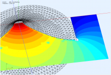
Well it does display the intensity along an arc but some far-field features are indeed observable only in the far-field (this is 1.5 x 2 m)...
(BTW, the white area beind the waveguide doesn't mean that there's a boundary. The waveguide really stands in free air - just the observation field is not present there at the moment, which has something to do with how this particular simulation is constructed.)
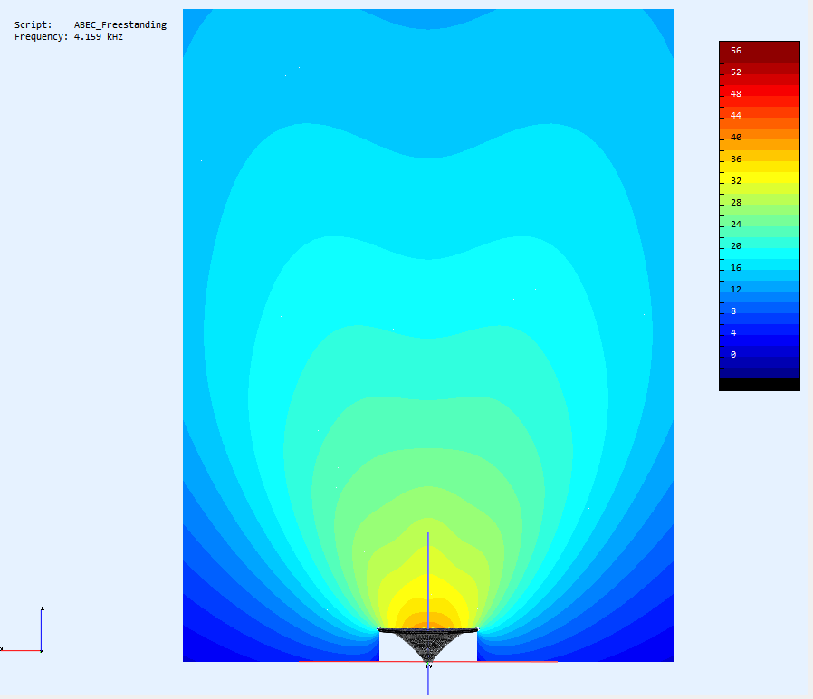
(BTW, the white area beind the waveguide doesn't mean that there's a boundary. The waveguide really stands in free air - just the observation field is not present there at the moment, which has something to do with how this particular simulation is constructed.)
Attachments


Last edited:

It looks like that the waveguide is mounted in a tube. There is no real edge diffration going on at mouth. The observation fields need to touch the backside of the waveguide - otherwise it is no free-standing calculation.
That's why I shared the complete BEM project for you to check for yourself. As you are obviously not able to do so, you will have to believe me.
Maybe I should explain this in more detail as it is really not that intuitive.
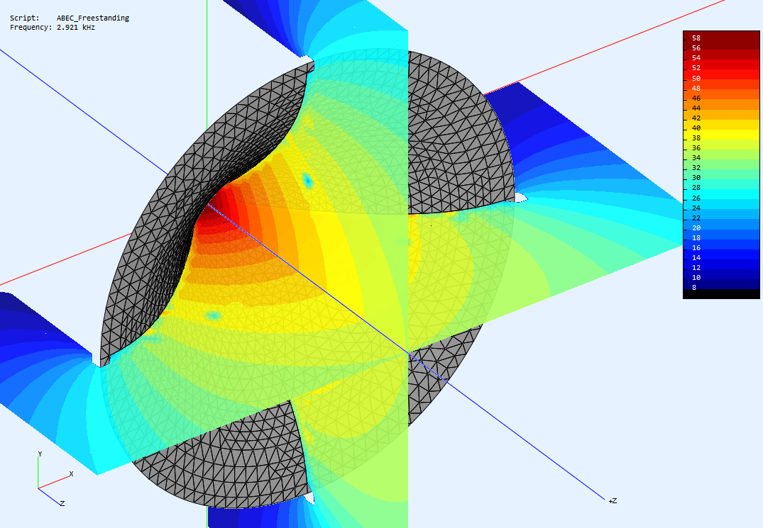
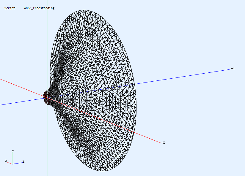
This is the interior of our waveguide, nothing surprising here (gray=wall surface; red=driving elements):
However, from the rear it looks transparent, and that's because it is actually acoustically transparent from the rear side of the surface - just as if it wasn't there (!):
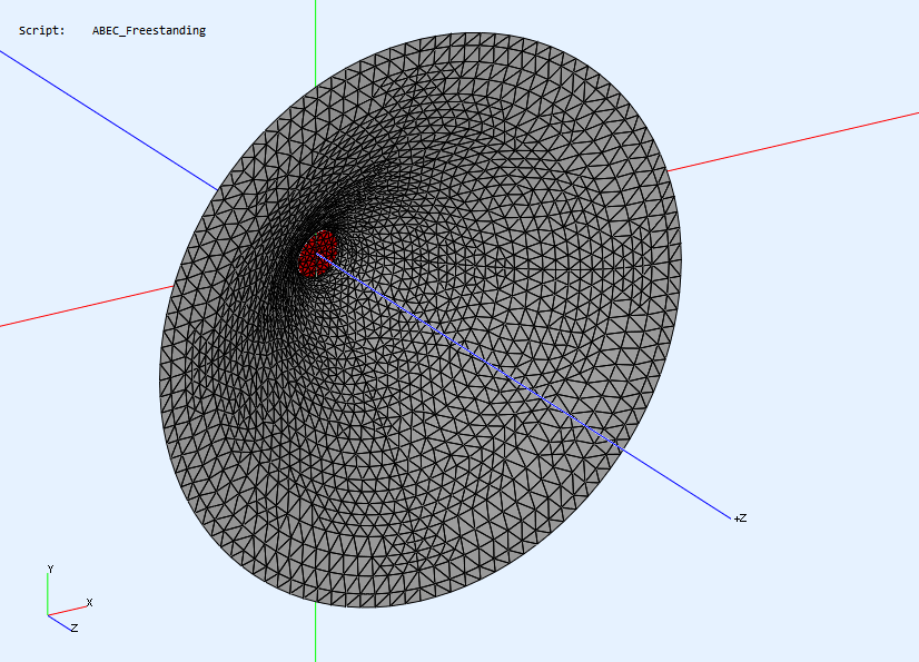
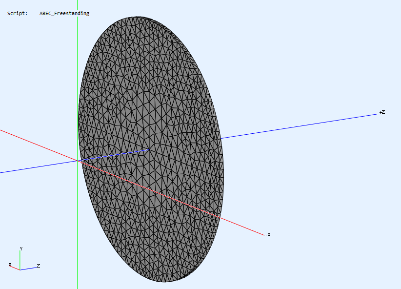
What we can do is to close the volume of the waveguide (which we have to do somehow) by adding a back side wall that is just a flat dics (!):

...which looks like this if we turn off the display of the waveguide interior:
From the front it then looks like this (the back side is visible but transparent again (!) - it's not really there):

This is just a convenient way how to simulate a free standing horn without the need to model its back side in full detail...
This is the interior of our waveguide, nothing surprising here (gray=wall surface; red=driving elements):
However, from the rear it looks transparent, and that's because it is actually acoustically transparent from the rear side of the surface - just as if it wasn't there (!):
What we can do is to close the volume of the waveguide (which we have to do somehow) by adding a back side wall that is just a flat dics (!):
...which looks like this if we turn off the display of the waveguide interior:
From the front it then looks like this (the back side is visible but transparent again (!) - it's not really there):
This is just a convenient way how to simulate a free standing horn without the need to model its back side in full detail...
Attachments


Last edited:
I have checked your project file:

This is the rear of the horn? Then people should be able to assess if this is an realistic free-standing calculation or nothing else than the trick Jörg Panzer described in one of his example files.
This is the rear of the horn? Then people should be able to assess if this is an realistic free-standing calculation or nothing else than the trick Jörg Panzer described in one of his example files.
This is exactly what Jörg Panzer recommends. It's actually a nice trick how to save some CPU time.
- Home
- Loudspeakers
- Multi-Way
- Acoustic Horn Design – The Easy Way (Ath4)