We'll need some sub millimeter 3d printers 
Thanks for the script, I'll see what I'm doing wrong.
*So far I can see that I have split the subdomains in length, instead of separating the channels.
And I discovered a "leak" a segment that didn't get imported.
Should really start using nodes instead of .DXF geometries...
Thanks for the script, I'll see what I'm doing wrong.
*So far I can see that I have split the subdomains in length, instead of separating the channels.
And I discovered a "leak" a segment that didn't get imported.
Should really start using nodes instead of .DXF geometries...
Last edited:
Let's say the geometry is not the issue but the path length, I think one could play around adjusting the delay of the sources for each path as a quick way of figuring out if the channel should be shorter, or longer...
I think I'm going to take this problem a bit back and do a series of exponential channels kind of like a multicell horn and play a bit with the delay on each segment.
I think I'm going to take this problem a bit back and do a series of exponential channels kind of like a multicell horn and play a bit with the delay on each segment.
Last edited:
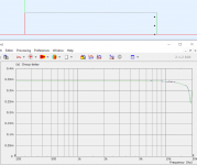
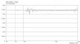
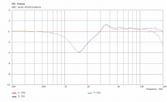
The travel delay at the end of each channel can be observed easily, see the pictures below. Simply terminate each channel with an absorptive element (100% damping). Even if the terminating element is not matching the velocity exactly, the error is still very small -
(The observation points are 118 mm from the source, i.e. approx 0.34 ms in time, which is shown in the group delay plot.)
(The observation points are 118 mm from the source, i.e. approx 0.34 ms in time, which is shown in the group delay plot.)
Attachments
Last edited:
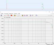
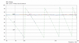
It's obviously related to the extraction from phase data - if I increase the number of points in that frequency band, it goes away (there are still some ripples, probably related to the dimensions of the tube, as they don't move at all) -
Attachments
Last edited:
You are right.
Did you try to sum the 3 subdomains in a common one?

I imported the script to AKABAK and played around a bit.
One ting I couldn't manage to do is to get the driving options to work.
In the driving options for each part of the drive, I tried to change the amplitude and introduce delay, just to see how that changes the pattern in the common "chamber"
It didn't make any difference.
Tried to plot the phase and still it didn't make a difference...
Did you try to sum the 3 subdomains in a common one?
I imported the script to AKABAK and played around a bit.
One ting I couldn't manage to do is to get the driving options to work.
In the driving options for each part of the drive, I tried to change the amplitude and introduce delay, just to see how that changes the pattern in the common "chamber"
It didn't make any difference.
Tried to plot the phase and still it didn't make a difference...
I can't comment on AKABAK.
For me the next step is to prepare a simulation of the whole plug placed in a sphere, radiating into an exterior domain. I want to be able to compare this to a simple spherical cap radiating in the same sphere (maybe it's not such a good idea after all due to the reflection at the outer edge, which won't be there in a waveguide, I'll see). Then I will start trying to optimize the design if possible. The outer channels will probably need to be narrower. But maybe the closed channels simulation already provides us all we need to know - we just want all the channel exits to have the same phase and amplitude along the terminating arc.
For me the next step is to prepare a simulation of the whole plug placed in a sphere, radiating into an exterior domain. I want to be able to compare this to a simple spherical cap radiating in the same sphere (maybe it's not such a good idea after all due to the reflection at the outer edge, which won't be there in a waveguide, I'll see). Then I will start trying to optimize the design if possible. The outer channels will probably need to be narrower. But maybe the closed channels simulation already provides us all we need to know - we just want all the channel exits to have the same phase and amplitude along the terminating arc.
Last edited:
Regarding the individual delays, in the example I posted all the channels have exactly the same length along the center line. I think you can't do much better than that. If there are still problems, and it seems there are, it probably won't be due to the lengths per se.
I don't know but I would assume that the same geometric lengths are the basic requirement - can't imagine it could help to adjust that. A more narrow channel would be less suspectible to internal diffraction, IMHO.
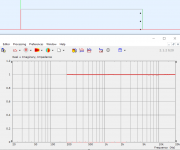
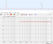
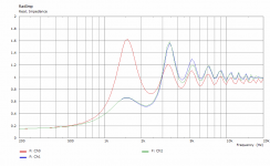
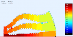
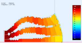
- Now I'm still trying to come up with some simulation framefork that would be useful for optimizing these things. I'm still not sure what to take away from the closed channels scenario, nevertheless here is a one more data set (channels terminated by a damping element) - I added pressure probes at the ends of the channels. Perhaps the bending has quite a big effect on acoustic impedance? (I believe that the wiggle is due to the wall impedance termination.)
Ch0 = center channel (SPL normalized)
Attachments
Last edited:
Quick search from the web found for example this paper https://arxiv.org/ftp/arxiv/papers/1703/1703.02171.pdf Design of an impedance matching acoustic bend
- which might not help here but indicates bend in pipe would affect the impedance / transmission.
Here some math, detuning effect of bends in a wind instrument https://hal.archives-ouvertes.fr/hal-00643184v1/document
- which might not help here but indicates bend in pipe would affect the impedance / transmission.
Here some math, detuning effect of bends in a wind instrument https://hal.archives-ouvertes.fr/hal-00643184v1/document
Last edited:
Hmm, not sure if mentioned earlier but isn't there similarity to the Danley Paraline and L-Acoustics V-DOSC stuff? Have you studied those if there is some insight what are the draw backs how to improve? They seem to be squeezed version of your tulip
Patric Bateman has done numerous threads on those, here is one An Improved Paraline. If I remember he wrote the idea is to keep the ducts so small the sound wave doesn't form inside the device but only after the exit, or something like that.
Edit, Tom Danley comments ~ Sunshine ~ and Danley Layered Combiner finds more stuff.
Sure these are for different application but might contain useful knowledge.
Edit,
PB thoughts how to get curved wavefront with a layered combiner.
Oh, you know...BG Neo10 | Page 8 | DiyMobileAudio.com Car Stereo Forum
edit,
Isn't the vanes in TH-4001 and a like horns for similar purpose as well?
Might turn out all the various ideas how to manipulate wavefront introduce HOMs as side effect.
Last edited:
I'm not familiar with any of those but I'm sure the same principles appear in all of it. What I'm trying to do here is very similar to the Tannoy Tulip, actually, as I realized - Tannoy | Product | QCI 6DC IW, i.e. to produce a spherical wavefront, overcoming the throat diffraction, if possible.
With the difference that I would use it with existing compression drivers, instead of making my own (which Tannoy in fact does). Sadly, there are very few measurements available of the Tannoy designs. I would like to see what's possible and how they succeeded, even though they use it in a coax.
With the difference that I would use it with existing compression drivers, instead of making my own (which Tannoy in fact does). Sadly, there are very few measurements available of the Tannoy designs. I would like to see what's possible and how they succeeded, even though they use it in a coax.
Last edited:
The new Tannoy Gold studio monitors seem to have tulip as well. Unfortunately no extensive off-axis data found... There are some in the brochure though https://mediadl.musictribe.com/medi...GOLD 7 P0CMZ_Product Information Document.pdf
Fortunately these are not too expensive, maybe purchase a set and measure? Anyone have them already?
Fortunately these are not too expensive, maybe purchase a set and measure? Anyone have them already?
Last edited:
Sometimes it becomes utterly mad. Can we believe it?
I'll have to work on it now, this was still only a quick&dirty try.
For absorption I'll need the terminating caps I guess.
I think this is the thin shape breakdown problem in BEM manifesting itself. If you look at the mapping of the fields, there is ‘leakage’ between the channels of the device.
Akabak has a dedicated non-uniform compensation option to try and resolve this, not sure if that’s in ABEC? It increases computation times and isn’t perfect, but might help.
The alternative is to simply use a scale model. It’s perfectly valid to do so, and will improve render times as well. If you blow the model up to a 10x scale, then you can modify the plots in VACS to see the behaviour at higher frequencies.
For what it's worth, tools like Siemens Virtual.Lab and it's hosts offer multiple types of BEM, as well as FEA and ray tracing to get around the different issues of standard BEM codes. Ansol Coustyx has seperate BEM codes for low, medium and high frequency, as well as fast multiple implementations that reduce sim times dramatically. It looks like that allows models with 100,000 elements to become feasible to render.
I'm curious what ABEC/Akabak uses at the backend, code wise. I know it's an indirect method only.
Anyway, look for the NUC option and try that. Otherwise magnifying glass time.
The other issue is the emulation of a perfectly absorptive or perfectly reflective rigid termination across the mouth of the device. For the former, an infinite baffle mounting and an interface to the external domain should be equivalent to a fully absorptive layer for the most part.
A rigid reflective termination will of course put a lot of reflected sound back down the channels, and their shapes will cause that to behave differently. It's a place where I wish you could plot isocontours of phase in 3D in this software.
mabat, in the vanes demo project [1] I see that boundary of subdomain elements of vane walls are configured as "driven" and only the the outer plug is configured as "fully reflective". Is this intentional?
[1] Acoustic Horn Design – The Easy Way (Ath4)
At least this might be a problem for ABAKAK that reports the following error during import of the ABEC project:
ERRORS ------------------------
"Driving" can be assigned only to whole sections (see at "Driving - Drive1")
"Driving" can be assigned only to whole sections (see at "Driving - Drive2")
"Driving" can be assigned only to whole sections (see at "Driving - Drive3")
Last edited:
- Home
- Loudspeakers
- Multi-Way
- Acoustic Horn Design – The Easy Way (Ath4)