Hello mlee! Woah film types are expensive. I'm hoping for an SMD 0805 sized capacitor.
Is that the "100R to Ground" that I've seen after the "DC Blocking Cap"? Is that what that is about? The 100OHM resistor connected to ground is a backup plan for the DC voltage to go if all else fails?
Hello SubSoniks! Yeah I'm using an ADAU DSP too for this project. Though the board I'm designing is a DAC/ADC board with PCM5242 and PCM1865. Fed via FreeDSP Expansion connector to the FreeDSP Aurora (or otherwsie in the future). I am also doing "live pro audio" and it too will have +/- 100 ft of XLR cables to instruments, mics, and other pro devices. So we are running down a similar path. I've been at this too long and I need a breakthrough. I'm hoping to get this PCM1865 ADC card right the first time (fingers crossed).
But the reason I brought this topic up is highlighted by your post of the Rane Schematic. There are VAST differences in schematics for inputs like this. I'm the type to look for "standards". I'll of course, just go off the datasheet, but I was hoping to stumble upon the "industry standard". Nope, I don't think that exists.
My only real question at this point is what CAP to use for that DC Blocker... Then I'll update my drawling for reference. I can't spend too much on this DC blocker, and I would prefer a 8085 size but I'm willing to compromise. Any advice on a specific part i should consider?
Very similar paths
") , my first go at pcb design so will see how it pans out, using easyeda which I've found the most straighforward.
, my first go at pcb design so will see how it pans out, using easyeda which I've found the most straighforward.I know next to nothing about smd caps, I have been using Panasonic FM throughhole, leak off resistor may be needed to stop them charging up.
My route is Suredsp adau1701 boards x 2, one each for left and right using the onboad adcs and 6 x pcm5102 for the Dacs, bought those in ready built, also looking at adding an aes50 board so really just building a backplane pcb. One cicuit I'm wanting is to drive a 2ma signal led from the adau1701 onboard dacs. One thing I really like about the PCM dacs were using is they both have on chip mute circuits, a big plus
are you using the PCM5242 to drive the ADC?
No they two chips (DAC/ADC) are just on the same board. Outputs to powered speakers/amps. Inputs from mainly microphones but also line level sources.
Last edited:
Given the option between film/X7R -- I'd be looking at a high quality bipolar electrolytic (e.g. Nichicon Muse ES, but all the major players have their series) with a sufficiently low corner frequency. X7R is just not linear enough for this application and film is $$ and big. They're not expensive.
I'd use the low ESR tantalums. They are small and don't cost that much. They will be better than the X7R in roughly the same footprint. Of course with that footprint you could try both.
mlee, thanks so much for finding that for me. The marketing material is clearly pushing me in that direction. It says it's meant for audio, and as you say, it's small and cheap.
Given the option between film/X7R -- I'd be looking at a high quality bipolar electrolytic (e.g. Nichicon Muse ES, but all the major players have their series) with a sufficiently low corner frequency. X7R is just not linear enough for this application and film is $$ and big. They're not expensive.
Hello DPH, yeah the bipolar electrolytic is what I would call a "standard". But they are also through hole, and relatively large. You know anything about these Niobium Oxide Capacitors?
NOJA106M010RWJ CAP NIOB OXIDE 10UF 20% 10V 1206
Product:
NOJA106M010RWJ AVX Corporation | Capacitors | DigiKey
Ad:
https://www.digikey.com/Web Export/Supplier Content/AVX_478/PDF/AVX_Caps.pdf
Hello Friends,
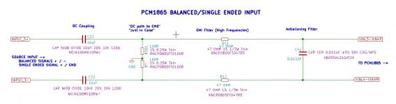
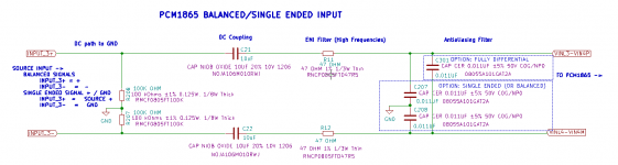
Sending an update to our discussion on the right selection of parts and plans for an input filter feeding into my PCM1865. Here is what I've drawn up.

Thanks for the input! Just a few more questions about this topic and I think I'll get my board built.
1. The "DC Path to Ground"... It's not in the PCM1865 datasheet. Include, or do not include? I would certainly appreciate reliability built into this project, so if it prevents blow-outs, I'm interested. Is the resistor selection ok?
2. Is my "single ended" detail ok? When connecting a single ended input, tie the minus pin of the differential path to GND... This should be good to tie it to ground right? Unfortunately, this configuration does diminish the PCM1865's ability to "MUX" inputs between plus and minus pins (dual single ended inputs can be mixed or mux'ed between plus and minus pins on the PCM1865 | you can mix a stereo input down to mono) but I decided I didn't need it.
Comments/Suggestions are welcome. Cheers.
Links:
DC Coupler:
NOJA106M010RWJ AVX Corporation | Capacitors | DigiKey
DC Path to GND:
RNCP0805FTD100R Stackpole Electronics Inc | Resistors | DigiKey
EMI Filter:
RNCP0805FTD47R5 Stackpole Electronics Inc | Resistors | DigiKey
Antialiasing Filter:
08055A101GAT2A AVX Corporation | Capacitors | DigiKey
Sending an update to our discussion on the right selection of parts and plans for an input filter feeding into my PCM1865. Here is what I've drawn up.
Thanks for the input! Just a few more questions about this topic and I think I'll get my board built.
1. The "DC Path to Ground"... It's not in the PCM1865 datasheet. Include, or do not include? I would certainly appreciate reliability built into this project, so if it prevents blow-outs, I'm interested. Is the resistor selection ok?
2. Is my "single ended" detail ok? When connecting a single ended input, tie the minus pin of the differential path to GND... This should be good to tie it to ground right? Unfortunately, this configuration does diminish the PCM1865's ability to "MUX" inputs between plus and minus pins (dual single ended inputs can be mixed or mux'ed between plus and minus pins on the PCM1865 | you can mix a stereo input down to mono) but I decided I didn't need it.
Comments/Suggestions are welcome. Cheers.
Links:
DC Coupler:
NOJA106M010RWJ AVX Corporation | Capacitors | DigiKey
DC Path to GND:
RNCP0805FTD100R Stackpole Electronics Inc | Resistors | DigiKey
EMI Filter:
RNCP0805FTD47R5 Stackpole Electronics Inc | Resistors | DigiKey
Antialiasing Filter:
08055A101GAT2A AVX Corporation | Capacitors | DigiKey
Attachments
My 2 cents and quick thoughts are:
- Put pulldowns to GND on the inputs before the capacitors. The eval kit has them and depending on source, they can be beneficial.
- After the 10uF caps make the resistors 47k ohms. That puts the high pass around 1hz and create a single ended input impedance. 100R is too low and will load the source.
- Keep all footprints. If you don't use them it is ok. If you need them it is a much harder modification. Better to err on the side of too many. It usually does not impact performance.
- The passive antialiasing filter might be a little hard/low. Even if the first pole low pass filter is ok in frequency, it can create pumping in the ADC which adds to non-linearity. But it may be ok. ADC dependent.
- Either change C41 to 2 caps to GND or add 2 more caps to GND. This will allow common mode and differential mode filtering. Might be useful in the single ended application to have caps to GND there.
Regarding the single ended GND pin. It might be better to pulldown the negative pin to GND through a resistor that matches the input impedance on the positive pin.
The above are just some rules of thumb that might help with a positive build. Feel free to use some or none of them as each project is different.
Looks like a fun project!
Thanks mlee! This has been helpful, and a lot of fun!

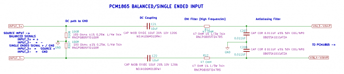
- The datasheet suggests a 100 OHM resistor in single ended mode, and 47 OHM resistor in balanced mode. I'll probably just keep it at 47 OHM, as suggested by mlee.
- The PCM1865EVM uses a "RESISTOR SMD0402 THICK FILM 100K OHMS 1/16W 1% ROHS" part for the "DC to GND"... I used a Thin Film, but I don't have any conclusive evidence that Thin is better than Thick here (or for the serial HP filter either). I heard through the grapevine that it's quieter.
- The antialiasing filter is now configured in "single ended" mode as referenced on the datasheet. mlee said, "Either change C41 to 2 caps to GND or add 2 more caps to GND. This will allow common mode and differential mode filtering." I'm unsure how to configure it for *both* besides removing one of the caps and bypassing it...
- I'm assuming I'll lose *some* common mode rejection with this antialiasing filter type (2 Caps to GND, vs 1 Cap to Plus/Minus). I believe that to be true because the two pins are no longer connected to eachother. I also assume that the PCM1865 will rectify that. The datasheet references a balanced input that isn't tied together at all, so I think I'm right that this is perfectly suitable. Of course I could bypass the connection as mentioned above, I don't know if I should go as far as to design a bypass jumper though...
- Having the inputs configured in this very flexible single ended mode exposes the ability for the PCM1865 to Mix/MUX each individual pin as a single ended channel... That just might come in handy. So I'd rather not bypass the antialiasing filter with 1 cap if suitable. i like having 2.
I do not think that any of the parts on the schematic are "extra". Everything is referred to on the datasheet, or included on the EVM module. Sure, the datasheet says the only thing I really need is the DC Coupler Cap, straight to the ADC. But it also recommends the optional antialiasing and EMI filter too. The benefits are very much worth it. I think we have a really high quality input setup here! I look forward to testing it! Thanks again for your help everyone.
- The datasheet suggests a 100 OHM resistor in single ended mode, and 47 OHM resistor in balanced mode. I'll probably just keep it at 47 OHM, as suggested by mlee.
- The PCM1865EVM uses a "RESISTOR SMD0402 THICK FILM 100K OHMS 1/16W 1% ROHS" part for the "DC to GND"... I used a Thin Film, but I don't have any conclusive evidence that Thin is better than Thick here (or for the serial HP filter either). I heard through the grapevine that it's quieter.
- The antialiasing filter is now configured in "single ended" mode as referenced on the datasheet. mlee said, "Either change C41 to 2 caps to GND or add 2 more caps to GND. This will allow common mode and differential mode filtering." I'm unsure how to configure it for *both* besides removing one of the caps and bypassing it...
- I'm assuming I'll lose *some* common mode rejection with this antialiasing filter type (2 Caps to GND, vs 1 Cap to Plus/Minus). I believe that to be true because the two pins are no longer connected to eachother. I also assume that the PCM1865 will rectify that. The datasheet references a balanced input that isn't tied together at all, so I think I'm right that this is perfectly suitable. Of course I could bypass the connection as mentioned above, I don't know if I should go as far as to design a bypass jumper though...
- Having the inputs configured in this very flexible single ended mode exposes the ability for the PCM1865 to Mix/MUX each individual pin as a single ended channel... That just might come in handy. So I'd rather not bypass the antialiasing filter with 1 cap if suitable. i like having 2.
Opps. Looks like PCM1865 has an input impedance of around 20k ohms so it must have internal pulldowns. I didn't look at the datasheet till just now.
Could leave out stuff if you are running out of space. I'd keep the pull-downs to GND before the coupling caps though.
I do not think that any of the parts on the schematic are "extra". Everything is referred to on the datasheet, or included on the EVM module. Sure, the datasheet says the only thing I really need is the DC Coupler Cap, straight to the ADC. But it also recommends the optional antialiasing and EMI filter too. The benefits are very much worth it. I think we have a really high quality input setup here! I look forward to testing it! Thanks again for your help everyone.
Attachments
Re: Antialiasing filter and common mode...
Is it possible to tie the two .01uF caps to eachother (for balanced), and then have a solder jumper to then tie those two to ground (for single ended)? The footprint could be an expose pad that could be sliced with an exacto knife to disconnect, or soldered back together to connect. Not a through-hole header or anything. Does having the two caps in series like this affect common mode rejection in a positive or negative way? Good idea or no?

Is it possible to tie the two .01uF caps to eachother (for balanced), and then have a solder jumper to then tie those two to ground (for single ended)? The footprint could be an expose pad that could be sliced with an exacto knife to disconnect, or soldered back together to connect. Not a through-hole header or anything. Does having the two caps in series like this affect common mode rejection in a positive or negative way? Good idea or no?
Attachments
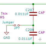
That schematic looks like it would present a 100 Ohm input impedance to any upstream equiptment??? As in post #32
Thanks for your comment. Is that because the DC Coupler? Do you recommend we change or remove it? It's on the PCM1865EVM...
Alright, I get it! Great idea. Thanks!

- Added optional Fully Differential Capacitor Footprint, won't be populated by default. Remove C207/C208 and insert C301 for fully differential.
- Fixed up DC path to GND with a 100 kOHM resistor.
- Added optional Fully Differential Capacitor Footprint, won't be populated by default. Remove C207/C208 and insert C301 for fully differential.
- Fixed up DC path to GND with a 100 kOHM resistor.
Attachments
- Status
- This old topic is closed. If you want to reopen this topic, contact a moderator using the "Report Post" button.
- Home
- Source & Line
- Digital Line Level
- ADC input Antialiasing Filter