I have a 1994 Ford F150 with a stock radio that includes a tape player that I'm currently modifying with a Bluetooth receiver. I've posted on other forums but haven't had any luck so far. I don't have a ton of experience with soldering or with modifying chips, so I don't mind anyone talking to me like I'm 5. I realize too that it could take a lot of explanation to teach someone with little knowledge, but I very much appreciate anyone taking the time. To someone of my skill, the more dumbed down the better.
The receiver comes with red and black wires for power, and then a red and a white rca cable that I've already cut off the RCA inputs to expose the wires. In my first attempt, I just spliced into the wiring for the tape player, but I could never get that working correctly.
In a perfect world, I'd find a way to toggle the "Tape Player" on and off to enter "Bluetooth Mode" (right now the tape player must be engaged to switch to tape mode, which I removed all the springs to keep it in tape mode. The problem there is that it can't switch out of tape mode. In hindsight, keeping those springs in would have been a better idea but they are all ruined now.) If that means removing most of the tape player, I don't mind that, especially since I've mostly messed that up with removing the springs. I don't know if this exists, but a toggle switch would be awesome that I could hide somewhere behind the tape door or something similar.
Here is a schematic that is close to what i have for my radio: https://www.diymobileaudio.com/attachments/ford-sound-2000_2006-sch-pdf.334305/
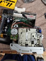
I am also adding photos that will hopefully help. The photo of the front of the radio isn't my radio, but that is what it looks like (mine is in better condition).
The receiver comes with red and black wires for power, and then a red and a white rca cable that I've already cut off the RCA inputs to expose the wires. In my first attempt, I just spliced into the wiring for the tape player, but I could never get that working correctly.
In a perfect world, I'd find a way to toggle the "Tape Player" on and off to enter "Bluetooth Mode" (right now the tape player must be engaged to switch to tape mode, which I removed all the springs to keep it in tape mode. The problem there is that it can't switch out of tape mode. In hindsight, keeping those springs in would have been a better idea but they are all ruined now.) If that means removing most of the tape player, I don't mind that, especially since I've mostly messed that up with removing the springs. I don't know if this exists, but a toggle switch would be awesome that I could hide somewhere behind the tape door or something similar.
Here is a schematic that is close to what i have for my radio: https://www.diymobileaudio.com/attachments/ford-sound-2000_2006-sch-pdf.334305/
I am also adding photos that will hopefully help. The photo of the front of the radio isn't my radio, but that is what it looks like (mine is in better condition).
Attachments
-
 94-96-Ford-F150-F250-F350-Truck-Bronco-AM.jpg371 KB · Views: 375
 -
 20220516_151103.jpg380.5 KB · Views: 220
 -
 20220519_161004.jpg634.1 KB · Views: 237
 -
 20220516_150931.jpg515.8 KB · Views: 243
 -
 20220516_151129.jpg568.2 KB · Views: 218
 -
 20220520_104705.jpg629.3 KB · Views: 213
 -
 20220516_151153.jpg511.5 KB · Views: 216
 -
 20220516_151144.jpg368.5 KB · Views: 221
 -
 20220517_131145.jpg346.7 KB · Views: 210
 -
 20220516_151046.jpg331.3 KB · Views: 216
 -
 20220519_131532.jpg413.5 KB · Views: 210
 -
 20220520_104958.jpg400.7 KB · Views: 201
 -
 20220519_131406.jpg279.7 KB · Views: 209
Sorry for my ignorance, but is there a way for me to find that out?What's the resistance between pin 23 of IC701 and ground?
I'm no expert on car cassette/radios, but my inclination would be to break into the circuit as late as possible. My first thought was to find the volume control - but as far as I can see, IC851 is responsible for volume control and other audio processing.
Can you identify this IC851 on the board? If so, find C857 and C853. If they are through hole devices this makes life somewhat easier. Try desoldering the end of these capacitors that is not connected to pin 14 or pin 10. Your audio from your Bluetooth receiver would then go to the now-unconnected side of these capacitors, L to C857 and R to C853, and don't forget to find to find a ground point for the screens of the cables from the Bluetooth receiver.
This will only work if you disconnect one end of the capacitors mentioned - don't try to take a shortcut and simply insert the signal at the nodes labelled TAPE+L and TAPE-R as the Bluetooth receiver will see the low output impedances of IC601 rather than the required high input impedances of IC851.
Pin 23 of IC701 is connected to ground.What's the resistance between pin 23 of IC701 and ground?

So I can see 857 and 853. There are some sort of posts (sorry if that isn't the name), am I desoldering and then removing those and then soldering the left and right wires of the bluetooth receiver in place of that? Or am I supposed to soldering from the other side of the board? Again, sorry for my lack of understanding.I'm no expert on car cassette/radios, but my inclination would be to break into the circuit as late as possible. My first thought was to find the volume control - but as far as I can see, IC851 is responsible for volume control and other audio processing.
Can you identify this IC851 on the board? If so, find C857 and C853. If they are through hole devices this makes life somewhat easier. Try desoldering the end of these capacitors that is not connected to pin 14 or pin 10. Your audio from your Bluetooth receiver would then go to the now-unconnected side of these capacitors, L to C857 and R to C853, and don't forget to find to find a ground point for the screens of the cables from the Bluetooth receiver.
This will only work if you disconnect one end of the capacitors mentioned - don't try to take a shortcut and simply insert the signal at the nodes labelled TAPE+L and TAPE-R as the Bluetooth receiver will see the low output impedances of IC601 rather than the required high input impedances of IC851.
Basically, the OP has to attach the output of the Bluetooth unit to the input of the existing unit, and make it work as if the tape is working.
This means always in tape mode, (bypassing the radio), and also the sensor that makes it think a tape is inside, that will have to be shorted out.
A lot of work... I would put a unit like above, FM clarity is terrific, and I can use memory cards as well as Bluetooth.
This means always in tape mode, (bypassing the radio), and also the sensor that makes it think a tape is inside, that will have to be shorted out.
A lot of work... I would put a unit like above, FM clarity is terrific, and I can use memory cards as well as Bluetooth.
Is an FM transmitter too easy?
https://www.amazon.ca/Transmitter-TEUMI-Wireless-Adapter-Bluetooth/dp/B07PVNTCN1/
https://www.amazon.ca/Transmitter-TEUMI-Wireless-Adapter-Bluetooth/dp/B07PVNTCN1/
I've done the FM transmitter trick several times, but the results have never been great. Maybe I should have spent more $$. 🙂
My goal is to use the original Head Unit to keep the car as stock as possible. I don't mind FM transmitters, but I feel like I'm constantly fighting with them.
I'm aware that this isn't a normal thing to do, but I'd like to be able to pull off the project and learn along the way.
I'm aware that this isn't a normal thing to do, but I'd like to be able to pull off the project and learn along the way.
I was trying to do the same thing with an old Mazda. The head unit was AM/FM CD Cassette. It has the option for a CD changer, and therefore a connector for the changer on the back. I found some adapters that could be plugged into that connector to give a Bluetooth signal. Instead of doing that, I bought a new Pioneer radio with Bluetooth and USB that sounded fantastic, but I hated it. Much too hard to use while driving, a terrible user interface. I put the old radio back in.
If you can find such an adapter, it's probably worth the try.
If you can find such an adapter, it's probably worth the try.
Looking at other replies here, I have to say that a Bluetooth to FM Transmitter would surely solve all your problems. I had no idea such devices existed, and at the prices on Amazon I might even give one a shot myself.So I can see 857 and 853. There are some sort of posts (sorry if that isn't the name), am I desoldering and then removing those and then soldering the left and right wires of the bluetooth receiver in place of that? Or am I supposed to soldering from the other side of the board? Again, sorry for my lack of understanding.
With regard to your reply about the capacitors, it's not clear to me what you are describing. Are the capacitors really connected to "posts" (i.e. pins)? I've attached a sketch in case this makes my initial suggestion easier to understand.
However, as NareshBrd points out, the alterations I showed are just the beginning. There is a lot of work involved, and an FM transmitter will do just what you want without making any alterations to the stock unit.

what about a tape adapter? it may even be possible to fit the bluetooth reciever in the "cassette".My goal is to use the original Head Unit to keep the car as stock as possible.
FM Transmitters are tough because where my cigarette lighter plugin is, they typically don't fit correctly.
I'm aware of how odd it is to go through all of this work, but it's something I'm willing to do. I am relying a lot on outside help, so I'll end up going as far as I can with outside people's assistance. I do appreciate everyone's time.
Ludus, those "posts" I was talking about are the capacitors (to really out myself on my lack of knowledge).
I am attaching 2 photos that will show where I think I'll be soldering the wires. The pink circles indicate where C857 and C853 are, and the yellow circles indicate where I think I'll be soldering the wires. One from the top of the board, and then the corresponding spot on the back of the board. My hope is that I'm able to solder the wires to the spots on the top of the board. Am I on the right track here? I do understand if people bail out on this thread.
Attachments


Re post #3.
You measure it with a multimeter.
If you can make this equal to the version that has the external loop, you may be able to leave the internals as they are (except for cutting a few traces) and use the external connections to feed the signal into the head unit.
You measure it with a multimeter.
If you can make this equal to the version that has the external loop, you may be able to leave the internals as they are (except for cutting a few traces) and use the external connections to feed the signal into the head unit.
The unit does not have the line I/O connections shown in the schematic? Because that's what would be easiest IF it had them. Your model does not, right?
- Home
- General Interest
- Car Audio
- Adding Bluetooth to Old Truck Radio