Hi All,
I recently had the joy of listening to a zero FB SET amplifier and have decided to have a go at building one. I am contemplating something like the attached schematic, which is I understand is reasonably tried and tested. I'll add a few of my own flourishes such as SS regulated supplies, but was otherwise hoping to copy the actual amplifier section more or less as published (with appropriate changes for the regulated supply). I understand it's pretty conventional but I am looking for an honest SET experience.
I'm interested to know if there's any reason to avoid this design or any other shortfalls? I note the absence of grid stoppers and seemingly conservative current in the driver tubes, any issues or suggestions here?
Appreciate any thoughts or suggestions or even alternative all triode designs to consider.
Many thanks,
Greg
Attachments

Last edited:

Check out Tubelab. He has his own subforum on diyaudio.
Lots of happy builders and support here.
What is your build experience?
Maybe better to start with an indirectly heated output tube, like in Tubelab's Simple SE.
A 300B amp can be great, but comes at a higher cost: the tubes themselves are more expensive than for instance an EL34. And the heater needs a proper regulated DC when you use a directly heater type like a 300B. Simple rectifier + cap like in your schematic is worse than AC.
How much power do you need? What speakers?
I second the Tubelab SSE. I built one last year and it's great. You can use a number of different power tubes, SS or tube rectifier, and a few other options. And, as Parafeed813 said, there's all the support you'll need right here in the diyAudio Tubelab sub forum. George, the designer/owner replies quickly to questions.
Tubelab SSE | Tubelab
https://www.diyaudio.com/forums/tubelab/
Good luck!
David
Tubelab SSE | Tubelab
https://www.diyaudio.com/forums/tubelab/
Good luck!
David
This particular design doesn't do any justice to the SET concept. It has some following indeed for the "oh those esoteric Japanese amps" reason, but still.I understand it's pretty conventional but I am looking for an honest SET experience.
First, it has reliability issues (none of the potentiometers and trimmers are protected from the wiper failure - and it's not as rare as some folks imply).
Second, the first two stages operate in the highly non-linear area, for the sake of being direct-coupled while still using relatively low B+.
Third, the 300B's "DC" heater supply is simply laughable.
I would look for other designs.
The 300B has a Hum Balance Potentiometer.
Real quiet DC filament supplies do not need a hum balance pot.
That should tell you something.
And, that eliminates one potentiometer and wiper.
For a non regulated, but very quiet 300B DC supply, I use the following circuit:
4A 6.3V filament winding
Low voltage drop Schottky Bridge rectifier
20,000uF first capacitor
2 Ohm 15W or 20W series resistor
20,000uF second capacitor
300B filament.
For the actual 2 Ohm resistor, I used a 3 Ohm 20W resistor, and then paralleled it with a second resistor that made the voltage at the filament = 5V.
Start with 12 Ohms, then 10 Ohms, 8 Ohms, 6 Ohms, 5 Ohms, until the filament voltage reads 5V
. . . Note: because there is a series resistor between the 20,000uF caps, the voltage of the filament rises slowly, so watch the voltage until it stabilizes, and try another resistor until you find a resistance value in parallel with the 3 ohm resistor that gives a warmed up filament voltage of 5 Volts.
4.9V to 5.1V is very well within the tube design limits, and the voltage will vary some with 300B tubes since their current draw is not exact (Boutique "Improved" 300B tubes draw more current than real 300B and real 300B copies; those 'improved' tubes will have far less than 5V in this circuit).
Adjust the voltage when your power mains voltage is at its average voltage (my power mains vary from 117V to 123V, so I wait until the power mains is at 120V, then I adjust the resistor until I get between 4.9V to 5.1V on the 300B filament.
I get less than 2mVrms ripple on that 5V supply (no hum at the amplifier output caused by 2mV ripple on the 5V supply).
Works for me.
As to the amplifier circuit, I paralleled a 12AY7. Individual 1k grid stoppers on each grid; individual 680 Ohm and individual 100uF bypass caps on the cathodes; Individual 1 k resistors in each plate lead and connect the other ends of the 1k resistors together at the plate load (an IXYS current source set to 6 or 7 mA); and RC coupling from the junction of the two 1k and IXYS current source to a 0.22uV 600V coupling cap, and the other end of the cap to the 300B grid, and the top of a 270k Rg to ground.
I used two 25 Ohm resistors from the 300B 5V filament ends, and joined the other ends of the 25 Ohm to a 1k self bias resistor that was terminated at ground.
A 470uF bypass cap was connected across the 1k self bias resistor.
A 3.5k or 5k output transformer loads the 300B plate; that is a tradeoff of max power, distortion, and damping factor, either one works well.
The B+ was adjusted to give about 300V plate to filament, and 60mA current. Do not forget the voltage drop of the output transformer primary DCR, 60mA x DCR Ohms, or you will not get 300V across the plate to the filament.
I built a pair of these more than a decade ago, but my friend in Japan has built a pair of these this year, according to my design, and he is pleased with the results.
Last edited:
Member
Joined 2009
Paid Member
Hi All,
I recently had the joy of listening to a zero FB SET amplifier and have decided to have a go at building one.
Appreciate any thoughts or suggestions or even alternative all triode designs to consider.
Many thanks,
Greg
can you get the details and/or design of the one you heard, could be a good starting point?
Thanks Everyone!
Looks like I need to look elsewhere for a design. I am pretty set on a 300B or similar though. Also considering the 6C33C, though I am put off by the supposed issues relating to socket life and the lack of current production.
Quite a few responses there so I will try to address the general gist of each of them.
Bigun: The current amp I have is a cheap Chinese SE EL34 amp. It was originally configured to run in ultra linear pentode mode, but I have connected G2 to A, and it is this "triode" mode that I really like and which has inspired me to make a "real" triode amp.
Parafeed: I have zero tube construction experience but am learning fast. I have designed and built dozens of SS amps from the ground up and also a Tesla Coil that runs from a 25kVA 11kV distribution transformer. So I am not new to amplifier design nor HV. I know 8W or so from a 300B is all I need and I would like the amp to be a genuine all triode amp - as discussed above I have already done the triode strapped pentode thing.
TG: Thanks for that. I agree about the operating point in the IPS, hence my question about the low current and voltage. I'm planning on fully regulated supplies in whatever I build but it sounds like this design is not worth pursuing as is.
Tubelab suggestions: Yep these designs look good but the SSE looks to be pentode only - unless that common cathode input stage can drive a 300B satisfactorily, please let me know?? The other tubelab amps have the FET based powerdrive which I am a little hestiant to try (even if it is techincally and sonically superior). Would prefer an all triode amp.
6A3sUMMER: Interesting design, sounds a bit like one of the elekit schematics I have seen. Do you have a schematic?
Thanks again everyone. I am also working on my own design which I will share soon.
GregH2,
My 300B amp did not do 8 Watts (well, it would be high distortion at that power).
I forgot, originally I used 25 Ohm resistors from the 300B filament ends to the 1k self bias resistor and bypass cap. But in the current schematic, I simply eliminated those two 25 Ohm resistors, and connected the negative end of the 300B filament directly to the 1k and bypass cap.
Ground loops are a major cause of hum.
Be sure to connect the B+ center tap directly to the bottom ends of the 2uF and first two 100uF caps (there were 2 in a single can).
That keeps the transient high frequencies in a local loop. Then a wire from there to the other sets of dual 100uF caps connect to the central ground.
The same goes for the RCA input jack, volume control, 12AY7 self bias resistors, and bypass caps. That has to be a local loop, before connecting from the local loop to the central ground point.
The 300B Rg, and 1k self bias resistor and bypass cap, and output transformer secondary common also connect in a local loop, and after that to the central ground point (which is connected to the chassis).
I built my mono-blocks on old Heathkit push pull EL84 integrated amplifiers; I only used the chassis and original power transformer.
The single filament winding means that the 12AY7 and 300B are powered from the same winding; that means the 12AY7 filament is at about +60V (OK).
My friend in Japan, built his completely from scratch. He used the One Electron UBT-2.
I have used Electra Print output transformers (3k and 5k), and One Electron UBT-2 (4.8k), for my 300B amplifiers. Those are the only ones I had for my 300B amplifiers over the years.
The schematics are attached (if it works OK).
Attachments


Last edited:
6A3sUMMER,
Thanks for that and for taking the time to respond.
The design seems simple enough to understand. Going to ponder on it for a bit but might have some more questions for you soon.
Cheers,
Greg
Thanks for that and for taking the time to respond.
The design seems simple enough to understand. Going to ponder on it for a bit but might have some more questions for you soon.
Cheers,
Greg
you can use AC no problem if have >93db use Coleman reg .... nice design here the new reference 300B amplifier
if you I will use an EML 300BXLS with some more B+ you can have more then 10w , iron monolithic transformer, tango tamura , lundahl
if you I will use an EML 300BXLS with some more B+ you can have more then 10w , iron monolithic transformer, tango tamura , lundahl
Last edited:
Hi All,
...I am contemplating something like the attached schematic, which is I understand is reasonably tried and tested. ...I understand it's pretty conventional but I am looking for an honest SET experience.
I'm interested to know if there's any reason to avoid this design or any other shortfalls? I note the absence of grid stoppers and seemingly conservative current in the driver tubes, any issues or suggestions here?
I recognize that diagram. That's from JC Morrison's "Tube Amp Primer" pamphlet, published ca. 1989. That circuit is probably copied from something in the Japanese magazine "MJ". I think you could do better, or that design can be improved upon. A single-ended 300B design is the classic. Not necessarily the 'best', but the classic.
--
The circuit is, except for the 300B, the same circuit as used in the SUN 2A3 amp (we built a variation). It is a dated design, there are more innovtive designs out there that sound better.
dave
dave
Actually the Sun Audio 2A3 and 300B SE amps share the same driver stages and overall topology, as well as the Morrison design indeed.
Since the bias voltage of a 300B is so 'tall', it makes a good candidate for DC coupling the plate of the driver to the 300B grid. One could RC-couple the input voltage amp stage to the driver stage (3 stage topology), which would put the RC coupling where it won't be likely to go into blocking.
Maybe 'stack' two power supplies, with the 'ground' of the 300B plate supply 'lifted' on top of the driver tube plate supply. Use a plate choke or CCS as the plate load for driver for minimum voltage drop.
Figure a 150V DC plate supply for the voltage amp-driver stages, then 400V to 450V DC sitting on top for the 300B (550V to 600V DC to ground, which is high, but not too crazy).
I whipped up a sketch. I could see the input tube being half a 6DJ8, driver being a triode-wired EL86, output tube 300B.
Just an idea. FWIW.
Attachments

For a single driver 2 stage approach check this out for a variety of good driver tubes.
300b with single stage driver, c3m or?
The EC86 comes up on a few threads - it's a true triode. I haven't seen any schematics with it but it shouldn't be difficult to knock one up. The Russian 6S3P or 6S4P are equivalents.
https://frank.pocnet.net/sheets/112/6/6S3PEV.pdf
300b with single stage driver, c3m or?
The EC86 comes up on a few threads - it's a true triode. I haven't seen any schematics with it but it shouldn't be difficult to knock one up. The Russian 6S3P or 6S4P are equivalents.
https://frank.pocnet.net/sheets/112/6/6S3PEV.pdf
you can use AC no problem if have >93db use Coleman reg .... nice design here the new reference 300B amplifier
if you I will use an EML 300BXLS with some more B+ you can have more then 10w , iron monolithic transformer, tango tamura , lundahl
Wow that looks nice. That D3A tube is pretty special! Thanks for sharing.
Thanks for the advice everyone. I have decided to pursue my own design and will share shortly...
Last edited:
Possible Amp Layout
Hi All,
I've been a bit distracted since I started this thread but finally have had a chance to think about it again. I still have some tweaking to do RE operating points and component values, but I'm contemplating something like this:
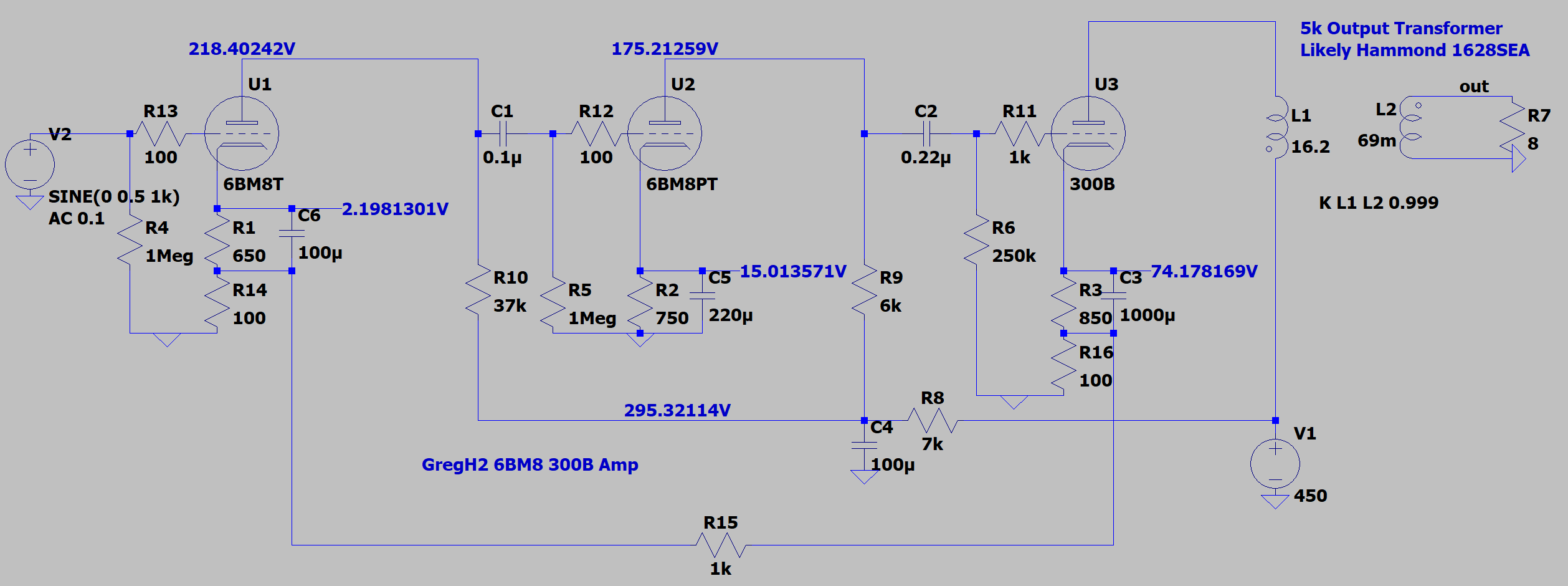
It uses GFB to stabilise the gain between channels. Given this should provide a reasonable damping factor I may elect to run a lower B+ and lower impedance output transformer for more power. This would also allow a smaller and lower wattage R8 value.
Any thoughts and comments would be appreciated!
Thanks,
Greg
Hi All,
I've been a bit distracted since I started this thread but finally have had a chance to think about it again. I still have some tweaking to do RE operating points and component values, but I'm contemplating something like this:
It uses GFB to stabilise the gain between channels. Given this should provide a reasonable damping factor I may elect to run a lower B+ and lower impedance output transformer for more power. This would also allow a smaller and lower wattage R8 value.
Any thoughts and comments would be appreciated!
Thanks,
Greg
... GFB to stabilise the gain between channels. Given this should provide a reasonable damping factor ...
NFB from power tube cathode current reduces damping factor.
...a smaller and lower wattage R8 value.
I don't see any reason R8 can't be 1k, about 15V drop, 0.23W running heat but use a 2W part for the start-up charge. The tube it feeds will still be within specs.
- Home
- Amplifiers
- Tubes / Valves
- Advice for first SET amp build