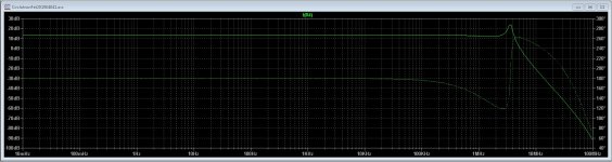
HI, cascode in vas increase bandwidth but require more compensation, do you try AC sim ?
Do you have books to learn how to spot the points to use?
thanks
What spots? I have learn LTspice in time and asking on LTspice tread, and still I do now now 30 procent of it.
Cascode needs almost always some compensation maybe through feedback.
have you schematic what you done.
regards
on your schematic with cascode :
https://www.diyaudio.com/forums/att...-allfet-circlotron-circlotronfet201904041-asc
I did not speak well, I wanted to ask you for a book where I could learn how to choose the right operating point for transistor, current/voltage
https://www.diyaudio.com/forums/att...-allfet-circlotron-circlotronfet201904041-asc
I did not speak well, I wanted to ask you for a book where I could learn how to choose the right operating point for transistor, current/voltage
I did set some caps for compensation.
The old way do not work save, special in the Mhz region, oscillating here will blow the amp. Do also now, laterals can also oscillate on there own, I have a small cap between drains and gates in the hybrid, and do work now for already 13 years
But reading docu,s about compensations is maybe a good idea.
regards
Attachments
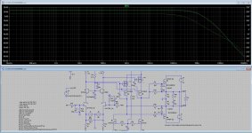
jfet biased like UGS/UP
15mA for vas
Thermally stable, still improvable with real CSS
You need enough current to drive the mosfets, with lateral things go easy but with verticals the driver need to be class A al the time to charge discharge gate capacitances and have low distortions.
You can use BJT if you want you let see with last schematic that works fine.
I have the vas working on 60mA or such, that give good driver with some balls. But maybe I am to negative thinking here. using a current siurce loaded vas then it follows always the 15 mA route.
regards
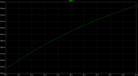
20N20 is double die
so your model is incorrect, with 2SK1058 it is 0.8V for 200mA
https://wakamatsu.co.jp/waka/rej03g0906_2sk1056ds.pdf
so your model is incorrect, with 2SK1058 it is 0.8V for 200mA
https://wakamatsu.co.jp/waka/rej03g0906_2sk1056ds.pdf
I can measure mine working amp, tomorrow because now it is dark and there are high voltages for the tubes present.
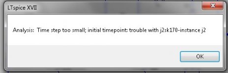
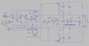
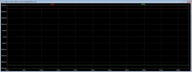
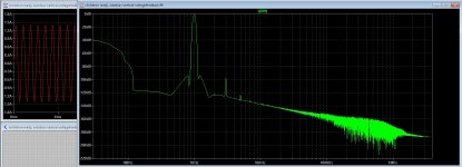
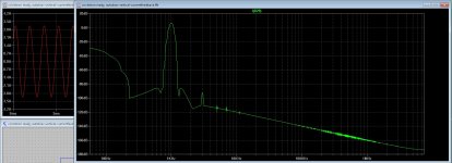
get the autobias current feedback not to work, the simulation stops timestep to small, moestly because of oscillation I think.
voltage feedback version does work, low HD even wit 220 mA idle and with low or high output voltage..
regards
regards
get the autobias current feedback not to work, the simulation stops timestep to small, moestly because of oscillation I think.
voltage feedback version does work, low HD even wit 220 mA idle and with low or high output voltage..
regards
regards
Attachments
Yes
But that is not a mosfet version vas, who has much more capacitances on input that is why I use a cascode to prevent this miller effect who can multiply capacitances, a BJT is lower in capacitance and it is a current driven device, mosfets are voltage.
But schemtic looks nice only the 510 ohms resistors makes a very low current drive possible so bandwidth is limited and distortion higher, you need to get enough voltage and current to charge discharge input capacitances of the lateral mosfets 20N20 that is why I have a extra driver for that in vertical version who idle on 60mA.
regards
Attachments

Last edited:
It's just an example of a circlotron without differential vas.
I was wondering if it was possible to use something other than a differential like simple vas, current mirror or folded cascode
we can look at passlabs X or XA : (all fet") )
)
https://www.diyaudio.com/forums/attachments/pass-labs/95994d1194305597-x100-backengineered-pdf
https://www.diyaudio.com/forums/att...1042404645-x100-backengineered-x100_input-gif
https://www.diyaudio.com/forums/att...backengineered-se-current-mirror-frontend-gif
https://www.diyaudio.com/forums/attachments/pass-labs/6079d1042646665-x100-backengineered-xa1_v3-zip
https://www.diyaudio.com/forums/attachments/pass-labs/5978d1042471075-x100-backengineered-xa1_v2-zip
I was wondering if it was possible to use something other than a differential like simple vas, current mirror or folded cascode
we can look at passlabs X or XA : (all fet
)https://www.diyaudio.com/forums/attachments/pass-labs/95994d1194305597-x100-backengineered-pdf
https://www.diyaudio.com/forums/att...1042404645-x100-backengineered-x100_input-gif
https://www.diyaudio.com/forums/att...backengineered-se-current-mirror-frontend-gif
https://www.diyaudio.com/forums/attachments/pass-labs/6079d1042646665-x100-backengineered-xa1_v3-zip
https://www.diyaudio.com/forums/attachments/pass-labs/5978d1042471075-x100-backengineered-xa1_v2-zip
Last edited:
It's just an example of a circlotron without differential vas.
I was wondering if it was possible to use something other than a differential like simple vas, current mirror or folded cascode
we can look at passlabs X or XA : (all fet
https://www.diyaudio.com/forums/attachments/pass-labs/95994d1194305597-x100-backengineered-pdf
https://www.diyaudio.com/forums/att...1042404645-x100-backengineered-x100_input-gif
https://www.diyaudio.com/forums/att...backengineered-se-current-mirror-frontend-gif
https://www.diyaudio.com/forums/attachments/pass-labs/6079d1042646665-x100-backengineered-xa1_v3-zip
https://www.diyaudio.com/forums/attachments/pass-labs/5978d1042471075-x100-backengineered-xa1_v2-zip
All you have send are just normal complementary amps, A circlotron is in fact two half ended amplifiers in bridge, when you seek on schematics who have only Quasi-complementary amplifiers, these vas are fase inverted, that is why you need a differential vas or a other way to make inverted signals who can drive the mosfets, enough current to overcome the gate capacitances and get enough bandwidth.
https://www.electronics-notes.com/a...n-sziklai-quasi-pseudo-complementary-pair.php
regards
- Home
- Amplifiers
- Solid State
- allFET circlotron