Amp starts, PS works, draws 1.1A on idle. Inputting any signal into the RCA --> amp goes into protect with CUR error.
I've read all of the threads for this amp in this forum.
I've lost a whole day measuring stuff and reading the schematics.
No shorted semiconductor parts, no shorted or opened diodes, blown caps or whatsoever.
There is no class D switching on the gates at the output mosfets/or the output of LO/HO IR2010S chips. Tracing stuff and comparing values to the service manual.
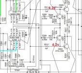
There is +4.2v at the collectors of Q301/Q302 instead of the -1.5v in the service manual.
IC301/IC302 have +4.2v at pin 6 -IN, instead of 1.5v in the service manual. OP amps supply voltages are correct.
Then IC303/304/305/306/307/308 voltages go haywire...
Firstly I thought it's MUTE error but Q305 voltage are right as in the manual.
Any help would be appreciated as i'm lost with this amp...
I've read all of the threads for this amp in this forum.
I've lost a whole day measuring stuff and reading the schematics.
No shorted semiconductor parts, no shorted or opened diodes, blown caps or whatsoever.
There is no class D switching on the gates at the output mosfets/or the output of LO/HO IR2010S chips. Tracing stuff and comparing values to the service manual.
There is +4.2v at the collectors of Q301/Q302 instead of the -1.5v in the service manual.
IC301/IC302 have +4.2v at pin 6 -IN, instead of 1.5v in the service manual. OP amps supply voltages are correct.
Then IC303/304/305/306/307/308 voltages go haywire...
Firstly I thought it's MUTE error but Q305 voltage are right as in the manual.
Any help would be appreciated as i'm lost with this amp...
Attachments

If you drive a signal into the amp, how far does it get through the circuit?
What is the DC voltage on each of the speaker terminals (black on secondary ground)?
The error in voltages is likely due to the fact that the feedback signal is not what it would be if the amp was working properly.
What's the DC voltage on all terminals of Q303?
What is the DC voltage on each of the speaker terminals (black on secondary ground)?
The error in voltages is likely due to the fact that the feedback signal is not what it would be if the amp was working properly.
What's the DC voltage on all terminals of Q303?
If you drive a signal into the amp, how far does it get through the circuit? - should I attach the LCD display for this test or no ?
What is the DC voltage on each of the speaker terminals (black on secondary ground)? - no voltages on the terminals
What's the DC voltage on all terminals of Q303?
1 - +4.8v
2 - minus 45v
3 - + 4.2v
Something else i've noticed - Q306 + Q901 + Q902 (2SC3421) are getting hot really fast.
What is the DC voltage on each of the speaker terminals (black on secondary ground)? - no voltages on the terminals
What's the DC voltage on all terminals of Q303?
1 - +4.8v
2 - minus 45v
3 - + 4.2v
Something else i've noticed - Q306 + Q901 + Q902 (2SC3421) are getting hot really fast.
I don't think the display board is required but I'm not 100% sure.
Those are regulators. You can expect them to get hot. Clamp them to a temporary heatsink if you are working out of the sink with the board.
Those are regulators. You can expect them to get hot. Clamp them to a temporary heatsink if you are working out of the sink with the board.
Okay...
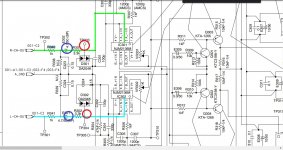
It's not the PRE-AMP section. I've traced the injected sinewave to here.
Blue circle is where it's still nice clean sinewave.
Red one is where it's only half of it and it's "below" ground. Like something is dragging it down.
Last picture is what I have at the output terminals. Something like a sawtooth wave below ground point --> this being an full bridge amplifier i was expecting a half rail voltage at each termial... ?!
Attachments


This is exactly what i did. I've put 30hz sinewave into the RCA. Maybe the word "injected" is not the right one.
If you connect a jumper from each speaker terminal to ground (preferably through something like an incandescent bulb, 2 bulbs), does your signal get through the op-amps?
Normally, I'd suggest closing the loop at the op-amp but these op-amps are not readily available.
Normally, I'd suggest closing the loop at the op-amp but these op-amps are not readily available.
Can I directly use 4 ohm speaker ? It's a really cheap one so even if something goes wrong i don't care about it.
When I make suggestions, I try to avoid doing further damage. The benefit of an incandescent lamp is that it has a really low cold filament resistance but if voltage gets applied, the resistance goes up, helping to prevent damaging anything. You can use jumper wires if you're careful.
If you connect a jumper from each speaker terminal to ground (preferably through something like an incandescent bulb, 2 bulbs), does your signal get through the op-amps?
So if I connect a sub as normally the client would do, is this going to be the same as connecting each speaker terminal to gnd through an incandescent bulb ? It's just easier for me. Wouldn't this also provide the feedback needed ?
Just asking, but i'll give it a go with the bulbs.
- Home
- General Interest
- Car Audio
- Alpine MRD-M1005 mono issues