I'm going to design two-way speakers. My initial rough design goal is a front 100cm tall by 50cm wide.


It will include the design of a trumpet with an exponential exit area approximated to a tractrix but rectangular in shape, built in wood.
The out of the TAD is 2 inches. 49 mm.


The area of the circle:
A=PI * R^2 will be divided into 5 equal parts.
A/5= (PI* R^2)/5
A=(R^2)/2 * [angle- sin(angle)]

It will include the design of a trumpet with an exponential exit area approximated to a tractrix but rectangular in shape, built in wood.
The out of the TAD is 2 inches. 49 mm.
The area of the circle:
A=PI * R^2 will be divided into 5 equal parts.
A/5= (PI* R^2)/5
A=(R^2)/2 * [angle- sin(angle)]
Attachments


Last edited:

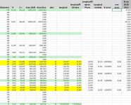
I test in Excel until they are equal to 3 decimal places. Angle -> Area/5
Retouch to correct 1mm width of the walls. I need to print in 3D printer. Removing the area of these separations from the total area. To calculate the area, the height in mm of the walls is measured in autocad.
For a width of 1 mm it gives the area this wall to be removed. Equal to the height of the wall.
A´ =A – [2* height(1/5) + 2* height(2/5)]
Final:
Angle -> A´/5 = 58,189
Angle -> 2* (A´/5) + height(1/5) = 79,387
Attachments


Next, you need to fit a tractrix curve by stretching or shrinking and scaling to fit the output shape of the TAD. Which already has a 75 mm first horn part. He has left me a horn about 47 cm long and 40 cm wide.
That assumes an area of the spherical cap of 129-115 mm. at the end of the horn.
That assumes an area of the spherical cap of 129-115 mm. at the end of the horn.
Attachments


That assumes an area of the spherical cap of 129,115 mm ^ 2.
I have calculated the area of the spherical cap using two formulas to see the precision of the Autocad measuring the dimensions of the drawing first with 5 decimal places.
A = PI * (r ^ 2 + H ^ 2)
A = 2 * PI * R * H
I have compared both values. The precision that I get with Autocad is 3 decimal places. On the other hand, with the 3D printer I have a precision of 0.05 mm. Two decimal places would be sufficient. I keep three to avoid rounding error.
We are going to approximate the spherical area of the cap to a cylindrical that would have the center from the output of the TAD. This area is divided by 5. We are going to convert the area of a spherical cap into the area of 5 rectangular surfaces with the same height of 49 mm.
The error of assuming 5 flat rectangles instead of curved ones is + 0.3% for the shortest section and + 0.2% for the longest section (one tenth of a millimeter). If you want to reduce the error, you can multiply the values by 0.9975. Making the error from + 0.01% to -0.08%. (the maximum error -0.018 mm., below the resolution of the printer
Attachments


In green you can see this second part of the horn in which there are 5 rectangular surfaces with a constant height of 49 mm. And with center the end of the tweet. They have been chosen so that the initial separation of the surfaces is greater than one millimeter. And the final one so that the final opening angle of the trumpet painted in blue is 500 mm. It is the width that I want to give to the box.
Attachments

There is a first phase that adapts the five equal surfaces into which the cylinder has been cut into the 5 rectangles. You have to make some guides so that Autocad maintains the correct 49 mm. height and area.
These figures show the first and second parts. I hope that with them you will understand for the first time what I am doing.
These figures show the first and second parts. I hope that with them you will understand for the first time what I am doing.
Attachments


For the third part of the horn (measured in blue) the distances of the arcs are taken and a curve spline is drawn to the right with the points and diameter of each point.
And then take the steps to be produced assuming 10mm wooden boards.
Horizontally it increases with a constant angle of 71 degrees. And vertically according to this curve obtained * ½.
Of course the steps have to be removed with sandpaper.
And then take the steps to be produced assuming 10mm wooden boards.
Horizontally it increases with a constant angle of 71 degrees. And vertically according to this curve obtained * ½.
Of course the steps have to be removed with sandpaper.
Attachments


It is important to prepare (in green) the lines that will serve as tangents to the spline curves (in yellow) that will serve as a guide in Autocad to draw the first part of the horn. And that the thinnest thickness can be printed. In this case it is 0.8 mm. The printer 3D printing at 0.4mm.
Attachments


Congrats!
This is an excellent idea I already have on my roadmap. My concern would be the thin walls in the throat region with respect to resonances.
This is an excellent idea I already have on my roadmap. My concern would be the thin walls in the throat region with respect to resonances.
Maybe I will check it and give the walls some more thickness. I made one for 1 inch motors and they don't resonate. But this is double the size.
In addition, the walls have curvature which removes vibrations.
But my holidays are over and I don't know if I will have time to redesign.
I wanted to make it somewhat wider and less tall. Now I am reviewing the aesthetics of the whole set a bit. I am bad at aesthetics and good looks.
In any case, when I print it I see if it resonates and I can do it again.
Attachments


The fin start at throat should normally be sharp as a knife, Yours look slightly rounded. Be aware not to cause reflections at throat.
Great work! I am very curious about your results.
Great work! I am very curious about your results.
It is sharp like a knife. But Docali is right, the walls are thin in the throat region with respect to resonances. In one inch I had no problems. But in 2 inches there is. To measure as a first prototype works for me. I probably redesigned the speaker, with thicker walls. But I have to start all over again.


Attachments


Nice! Great to see 3D printing and styrofoam for rapid prototyping. I used to use a styrofoam horn.
- Home
- Loudspeakers
- Multi-Way
- Altec 416-8B + TAD 4001