Hi. Anyone could recommend a good AB amplifier rail voltage regulator circuit Pos/Neg? I'm looking for about 75-80 Vout, Iout approx 1.5-2A peak, bias approx 500-600ma.
There is always the classic Transistor Pass regulator with op-amp and zener reference diode, but I'm looking for the expert advise.
I'm not debating here of the merit of using a rail reg or not, but I would like to try that in one of my amps.
I thought of using something similar to a Jung Reg, but without the pre-reg, using On Semi MJL3281A 200V, 15A pass transistor, instead of the lower power D44H11 as shown (PNP complimentary MJL1302A is available for the negative reg) such as this schematic. But Jung reg may be overboard for an amp rail regulator.
Thanks in advance
SB
Attachments

I gently suggest that you give some thought to using two pass devices instead of one. With, of course, the appropriate ballasting resistors in series with the emitters and stopper resistors in series with the bases, to ensure that the pass transistors share current equally despite minor differences in temperature and minor differences in VBE.
Now you can be certain you're well within the Safe Operating Area of each transistor, even when charging the output capacitors at power up (Vce = 80V, Ice = gigantic and enormous).
I'd recommend using a medium bandwidth opamp (1 MHz < GBW < 20 MHz) rather than the AD797. Or, perhaps better still, a 4 transistor discrete amplifier built of MPSA42s and MPSA92s which are rated for 300 volts. If you use an IC opamp you'll need to down-regulate a special ~ 25V power supply so you don't overvolt the chip.

I would have thought using PNP series pass devices (or P channel FET) for the positive rail and vice versa for the negative rail would give much better performance and also be far less reliant on having to have a substantial voltage differential (Vin -Vout) to work well.
I'm not so sure a power amplifier needs or wants a low-voltage-drop regulator. For example the legendary Mark Levinson ML-2 power amp's voltage regulator, drops a minimum of 3xVBE. Its positive regulator is built with NPN bipolars and its negative regulator is built with PNP bipolars. Since the input voltage is anything but stable (thanks to 120 Hz ripple), you don't have any way to guess how low the raw DC input voltage might droop, so you don't exactly know how high you can set the regulated output voltage. So you guess conservatively and that conservatism allows the use of a higher-voltage-drop regulator.
See page 3 of the ML-2 schematics and look at the four transistors inside the dashed lines labeled NRP-1 Heatsink and PRP-1 Heatsink.
See page 3 of the ML-2 schematics and look at the four transistors inside the dashed lines labeled NRP-1 Heatsink and PRP-1 Heatsink.

The ML-2 Schematic is very interesting. Current source to bias the Vref zener (to improve CMRR), I saw this trick used often by great designers such as Borbely. Same Vref is used by both Pos & Neg regs. Complex amplifier, let have a look...
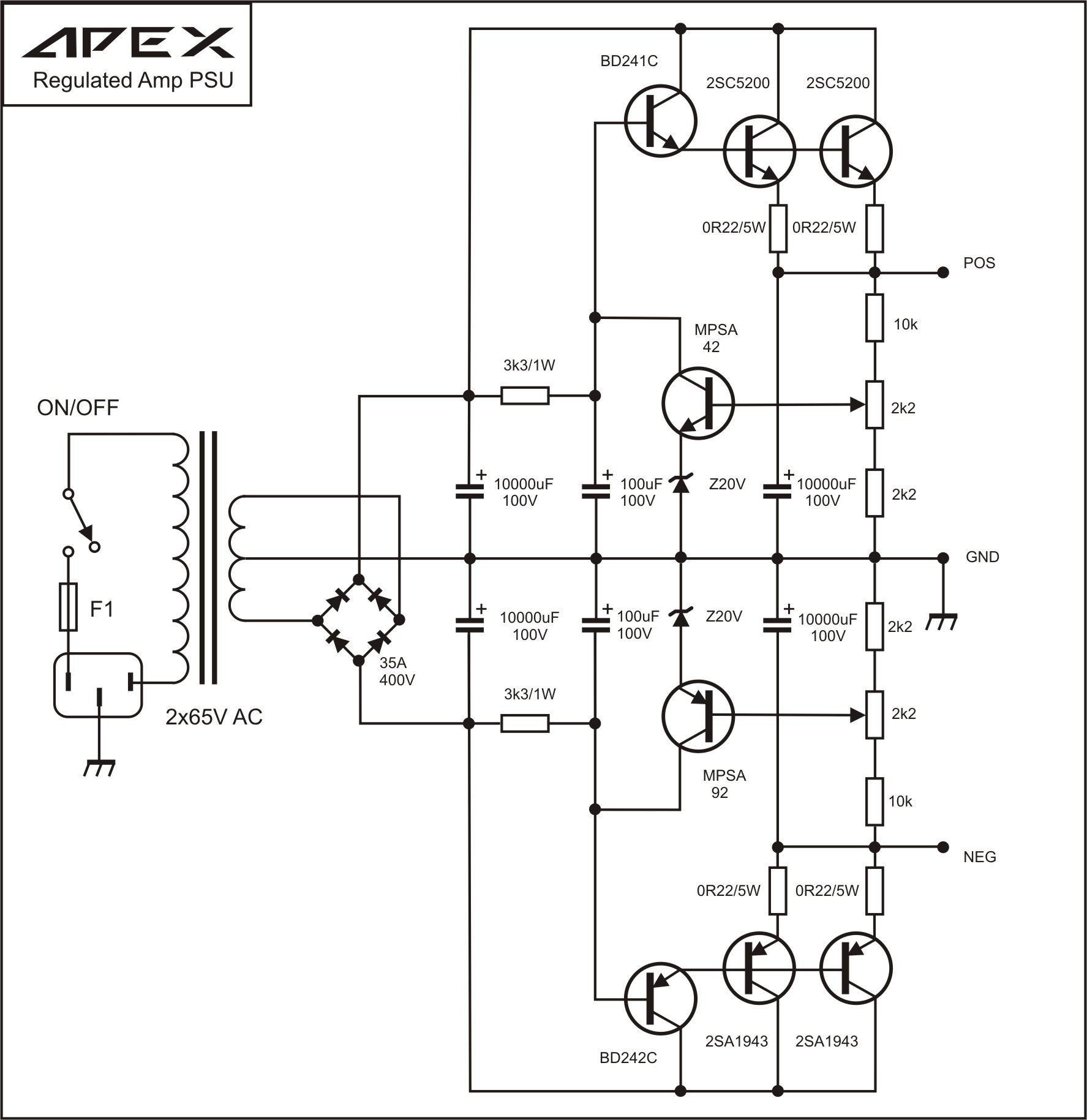
Thanks xrk971 for the Apex reg, interesting circuit as well as usefull part choice
Thanks xrk971 for the Apex reg, interesting circuit as well as usefull part choice
Last edited:

- I prefer to follow the Quasimodo orthodoxy by connecting (Ca series Ra) directly across the transformer secondary, i.e., between AC1 and AC2 on the schematic
- I prefer to establish a minimum DC bias current in Q3 by adding a new resistor from Q3 emitter to OP1.
- I prefer to choose Q3 having a max voltage spec, at least as large as Q1's max voltage spec.
- I prefer to add a new 24K resistor from +90V to ZD1 cathode, thereby establishing a minimum bias current of (70V / 24K) = 2.9 mA in ZD1. This resistor should be rated at least 0.5 watts (or fit two 12K, 0.25 watt resistors in series).
- If your simulator supports .STEPped values of components, I suggest you run AC analysis simulations with C12 = 15pF, 200pF, 2nF, 20nF, 0.2uF, 2.0uF, and 20uF. Observe what happens to the AC output impedance of the voltage regulator, as you .STEP the value of C12.
But my tastes and preferences might not match anyone else's.
You're suggestions are as good as none from me 😉 For Q3, MJE340 is 300V
I prefer to establish a minimum DC bias current in Q3 by adding a new resistor from Q3 emitter to OP1, What value would you suggest, for R5a I put 1K? Instead of R2a, 24K, isn't better to use a current source, I have J511 in stock?
How about this one?
I prefer to establish a minimum DC bias current in Q3 by adding a new resistor from Q3 emitter to OP1, What value would you suggest, for R5a I put 1K? Instead of R2a, 24K, isn't better to use a current source, I have J511 in stock?
How about this one?
Attachments

Last edited:
Please post your design calculations here, for the amount of power a J511 will dissipate in your circuit?... better to use a current source, I have J511 in stock?
_
Attachments

Member
Joined 2009
Paid Member
I have always read that it's unlikely a regulator is needed or provides much benefit for a Class AB power amplifier - and would end up being as expensive and complex as the amplifier itself for little to no gain. If the power amp has good PSRR that is.
I have always read that it's unlikely a regulator is needed or provides much benefit for a Class AB power amplifier - and would end up being as expensive and complex as the amplifier itself for little to no gain. If the power amp has good PSRR that is.
JLH used regulated PS in his Class AB 80W mosfet amp and it's equipped with all needed protection.
I use successfully in my amps a PS regulator with the similar concept(not with fix voltage, but more like cap multiplier), you can see the schematic and PCB here: http://www.diyaudio.com/forums/solid-state/243481-200w-mosfet-cfa-amp-92.html#post4580606
I designed a two pass-transistor based regulator and cap-multiplier board if you want a simpler circuit that might do the job for you:
http://www.diyaudio.com/forums/powe...tance-multiplier-over-voltage-protection.html
Look past the first page for the final circuit.
No protection included! For inspiration only.
http://www.diyaudio.com/forums/powe...tance-multiplier-over-voltage-protection.html
Look past the first page for the final circuit.
No protection included! For inspiration only.
I think for power amplifiers, a cap multiplier is a worthy option
1. Minimal input output Vdrop and therefore low power dissipation
2. 30 to 40 dB ripple rejection (see e-Amp write-up for a scope shot of input vs output)
3. Very simple and cost effective
1. Minimal input output Vdrop and therefore low power dissipation
2. 30 to 40 dB ripple rejection (see e-Amp write-up for a scope shot of input vs output)
3. Very simple and cost effective
Good PSRR is good to have, of course, but when you clip (and you will often, at any reasonable volume level and listening to non compressed music) PSRR becomes ZERO, as in 100% of ripple appears modulating waveform peaks.
You can minimize this, either playing at a gentle volume (say, 10% average vs. RMS rating) or listening to highly compressed music.
You can minimize this, either playing at a gentle volume (say, 10% average vs. RMS rating) or listening to highly compressed music.
To replace the weird PC14 series voltage regulator/current limit in my dynakit ST120, I'm using one stack of 12v 1.3 watt zeners to 72v, going to bases of five TIP142 darlingtons in parallel with .22 ohm load sharing emitter resistors. Series resistor on the zeners was two series 910 ohm 1 W resistors (I didn't have 1.8 K 2W)
But I have 10 v to waste. Low voltage drop is not a goal. This gets me 69.5 v.
TIP142 were $1.11 the day I bought from newark, so they are genuine. Whereas MJL4302 is over $4 and fairchild 2SC5200 are the same and 2SA1943 PNP is not stocked. I'm trying to get 12 A peak out of this. The heat sink is salvage of an old pentium 3 CPU, about 4"x3"x1".
The amp board I'm building has ****y PSRR, but about 50 less wires and 6 less transistors than something with. It's got to fit on a 3x5 card without surface mount tools & skills. Also with no center tap on the transformer, most of the speaker capacitor circuits out there don't have PSRR.
Last edited:
- Status
- Not open for further replies.
- Home
- Amplifiers
- Solid State
- Amplifier Rail Voltage Regulator