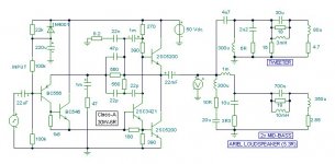
Another amplifier topology from Mr. Jean-Marc Plantefève.
Hi, Argo -
I came up with that topology some time ago, but with feedback taken from the output to the jfet sources.
Hi jam,
I understand then that the Cs are being used to deliberately cause phase shift, which will increase delay. This means that the amplifier will be slower (relatively) to counter loudspeaker induced back emfs and additional reactive loading.
Until the circuit is simulated with the electrical equivalent of a real world loudspeaker it cannot be assumed to be satisfactory just because it tests okay with 8R and maybe a parallel C.
For example
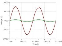
I could recommend the attached class-A JLH 30W-6R derivative for its flat responses and 0.005% thd at af frequencies. It will sound superb and better than non or low NFB types with full range drivers or with more complex hi-fi types at relaxed listening levels, but it will be unable to cope with complex dynamic loudspeaker induced back emfs at enthusiastic listening levels.
As there is only 50nS propagation delay for the NFB loop to fully respond and the response is not inductive, it does not lose control when it distorts. Also attached. This amp is struggling well below its full power output as most class-As do; maybe one of Millwoods mosfet variants would cope better from a power point of view.
The loudspeaker illustrated here can be found on the Web.
It is know to sound clean when driven with valve amps, but rarely so with transistorised 'efforts'.
With this more realistic load different amplifier circuits react badly at different audio frequencies, typically around 55Hz, 2kHz and 10kHz. Some are affected within the first cycle of reproduction, others the second, and those with internal closed loop delay can react like an inductive spring to generate higher frequencies than those that the amplifier drives the speaker with, especially on transients and first cycle sinewaves.
I have concerns for several circuits on this string, and feel that designers should be very careful about believing 8R loaded simulations with or without additional C or L connection. It is loudspeakers we listen to, and loudspeaker equivalents we should be simulating with.
Don't give up on that circuit subwo1, I think it has potential.
Cheers for now ......... Graham.
I understand then that the Cs are being used to deliberately cause phase shift, which will increase delay. This means that the amplifier will be slower (relatively) to counter loudspeaker induced back emfs and additional reactive loading.
Until the circuit is simulated with the electrical equivalent of a real world loudspeaker it cannot be assumed to be satisfactory just because it tests okay with 8R and maybe a parallel C.
For example
I could recommend the attached class-A JLH 30W-6R derivative for its flat responses and 0.005% thd at af frequencies. It will sound superb and better than non or low NFB types with full range drivers or with more complex hi-fi types at relaxed listening levels, but it will be unable to cope with complex dynamic loudspeaker induced back emfs at enthusiastic listening levels.
As there is only 50nS propagation delay for the NFB loop to fully respond and the response is not inductive, it does not lose control when it distorts. Also attached. This amp is struggling well below its full power output as most class-As do; maybe one of Millwoods mosfet variants would cope better from a power point of view.
The loudspeaker illustrated here can be found on the Web.
It is know to sound clean when driven with valve amps, but rarely so with transistorised 'efforts'.
With this more realistic load different amplifier circuits react badly at different audio frequencies, typically around 55Hz, 2kHz and 10kHz. Some are affected within the first cycle of reproduction, others the second, and those with internal closed loop delay can react like an inductive spring to generate higher frequencies than those that the amplifier drives the speaker with, especially on transients and first cycle sinewaves.
I have concerns for several circuits on this string, and feel that designers should be very careful about believing 8R loaded simulations with or without additional C or L connection. It is loudspeakers we listen to, and loudspeaker equivalents we should be simulating with.
Don't give up on that circuit subwo1, I think it has potential.
Cheers for now ......... Graham.
Attachments
Christer,
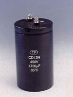
DC blocking cap, indeed. Those things should be only be used when necessary besides the impedance of the current feedback network is so low you will need a huge cap..................(like on of these to get a good response)..... It would be like attaching one huge antenna to the feedback circuit.")
Regards,
Jam
DC blocking cap, indeed. Those things should be only be used when necessary besides the impedance of the current feedback network is so low you will need a huge cap..................(like on of these to get a good response)..... It would be like attaching one huge antenna to the feedback circuit.
Regards,
Jam
Attachments
Jam,
Yes, you're right. I didn't remember the gain resistor was that
small. It would probably have to be a servo then, or just let it
freewheel as is obviously intended. I wonder if any of those
who have built the Zen-/Mos-/Buzquito has measured the DC
drift?
Still, 450V is bit highish for a DC blocker, isn't it?
Jam,
I would still prefer to have some protection for the speakers,
regardless of which amp design it is, but that is balance
between audiophilia and risk analysis where opinions will
differ. If you can afford to risk blowing your speakers, then
go for it. Maybe the crowbar solution would be acceptable
if you don't like relays?
It is nice to hear the DC didn't drift, though. Did you take much
care to match components, the VAS BJTs and the OPS MOS's?
BTW, now that you've reminded me that the gain resistor was
a decade lower in resistance than I remembered, I think the
mod I suggested makes even more sense from a theoretical
point of view, at least if the design is intended as a "true" CFB
and not some kind of pseudo-CFB. Maybe there is some delibarate
trade-off, though, and the designer actually wants this behaviour
for sonic reasons? Why do I keep envisioning a PCB with a lot of
extra components everywhere and a lot of jumpers?
I would still prefer to have some protection for the speakers,
regardless of which amp design it is, but that is balance
between audiophilia and risk analysis where opinions will
differ. If you can afford to risk blowing your speakers, then
go for it.
Maybe the crowbar solution would be acceptableif you don't like relays?
It is nice to hear the DC didn't drift, though. Did you take much
care to match components, the VAS BJTs and the OPS MOS's?
BTW, now that you've reminded me that the gain resistor was
a decade lower in resistance than I remembered, I think the
mod I suggested makes even more sense from a theoretical
point of view, at least if the design is intended as a "true" CFB
and not some kind of pseudo-CFB. Maybe there is some delibarate
trade-off, though, and the designer actually wants this behaviour
for sonic reasons? Why do I keep envisioning a PCB with a lot of
extra components everywhere and a lot of jumpers?
jam said:Christer,
No special matching ......... I was told by my supplier that outputs were matched only as P or N channels.
Maybe you need to build one and see if your mod helps.
Regards,
Jam
Some day I hope to get around building one. It is on my toplist
of designs I'd like to try. Since the mod is so simple to accomodete
with jumpers to switch between modded and original I most
likely will include it. However, this was just one of several ways
to achieve the intended effec that struck me, but since it seems
so straightforward and makes it so simple to switch between
versions, I think it might be the preferred way to do it. I haven't
honestly made any calculations or simulations yet, though.
Anyway, I absolutely agree the mod ultimately has to be
implemented and tried in practice. Anyone who is less impatient
with the soldering pen than me, feel free to try it out if you
think it might have some merit.
How did you like the sound of the amp? One of the french
forum members who built the Zenquito version seemed
very satisfied with it.
Jam,
I think one of the french guys building it described the sound as
tube-like. I don't know, but maybe that is consistent with your
assesment of lacking punch. May I ask what kind of you music
you listen too, since I happen to think that does influence ones
assesment of equipment. I always wish more people would add that
piece of information, since it helps to decide what degree of
relevance their listening impression might have for ones own
taste in music.
Output protection is really tricky. Almost all power relays are marginally lousy. Output fuses suck! However, rail fuses, or even better: dual DC circuit breakers work OK. E-I active protection usually causes big problems as well.
Parasound uses output protection relays because we have to. Our amps are usually pretty powerful with lots of peak current. Without protection, too many broken speakers would happen because of audiophile mistakes as well as an internal amp problem, and we would be held responsible.
Parasound uses output protection relays because we have to. Our amps are usually pretty powerful with lots of peak current. Without protection, too many broken speakers would happen because of audiophile mistakes as well as an internal amp problem, and we would be held responsible.
John,
As for output fuses, even Slone dismiss them and claim they
cause thermal distorsion, so that seems a definite no-no.
There are a kind of relays having dual contacts, one of them
makes before and breaks after the other one and is made of some
material that can take heavy loads. The other one is usually
plated with some material that cannot make/break heaavy loads, but
have much better electric properties. That is, the first one handles
the potential arc, and the other one connects/disconnects only
when there already is contact through the other contact so that
no arc can arise. These are supposed to be much better but seem
hard to source, but I suppose you have tried those ones too?
What do you think of crow-bars, ie. thyristors that short the
rails to blow the fuses when the DC level becomes too high?
Just an idle thought: could current sense inductors be used? The catalog descriptions and datasheets claim they have no effect on the line being monitored. When the current reaches a predetermined level, perhaps the resulting output voltage could turn on a transistor that then reverse biases the output devices enough to shut them off? I'm just thinking this off the top of my head because the Digikey catlog fell open on the page with these things the other day and I've been wondering what they might be good for.
Christer,
The sound was tuble like without being overly rich. The highs were excellent, to me much better than most solid states and tubes. The bass just lacked a little bit of heft but not bad,at all. Also note the speakers I was using at the time wer pretty low impedance.
Regards,
Jam
P.S. To me the amp with the best bass is the Pass A40 (within its power rating), hands down.
- Status
- This old topic is closed. If you want to reopen this topic, contact a moderator using the "Report Post" button.
- Home
- Amplifiers
- Solid State
- Amplifier Topologies