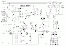
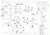
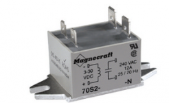
Yes, sorry, they have to be chosen according the power of the amp (> than voltage rails and < than max mosfetsV ).are d21 and d22 zeners? i ask because symbol is for shottky diode.
You can use Transient-voltage-suppression diode like:1.5SMC82A, or any zener allowing enough current for 1ms. We will see all this together when we will set precise BOMs.
I will change a little some LED's resistance (red, yellow, green) to minize the number of wires between the board, and the front amp.
Done.
4 Wires to be on a connector, like flat cable ?
There is an error to resistance r30 (in your schematic) set at 2K shall be at 1K.
I will change a little some LED's resistance (red, yellow, green) to minize the number of wires between the board, and the front amp.
Done.
4 Wires to be on a connector, like flat cable ?
There is an error to resistance r30 (in your schematic) set at 2K shall be at 1K.
Last edited:
Member
Joined 2009
Paid Member
Honestly, I think you're making a mountain out of a molehill by insisting on such a low Rds on, a higher value (within reason) will be no issue and you'll have more choices of parts and lower cost. I think there are better things to focus on for 'ultimate' performance.
Damping factor is over-rated in my opinion, and in the opinion of many others. For example, read what Rod Elliot has to say. And a slighter higher Rds on will have negligible impact on damping factor when you figure in the resistance of the pcb traces in your amplifier, the resistance of the wire to your speaker and finite feedback factor.
Distortion - small Rds on in series with the output will have no relevant impact on this parameter.
It is not a problem, the board will be supposed to be populated according each one's needs.
The first static relay, by example, is only necessary when the power-on is remote, etc.
The *choice* of using one up to 3 slides of paralleled MOSFETs cost nothing but a little room on the printed board.
Can be absolutely necessary if you need this protection for a very high power amp, with high voltages rails, IE high voltages MOS, IE, high RDS-on.
I don't totally agree with you on that point: the non linearity of the MOSFETS with signal levels and currents is not negligible. Low rds ones have the same non linearities, but the impact is less prejudicial, easy to understand why.
Damping factor is not a function of the parts (traces) before the feedback point, IE, loudspeaker plug in the amp. If we could take the feedback point after the MOS, it would be perfect. Sadly, it is impossible.
Listen, my enclosures have flat impedance curves. Supposed to be insensible to diameters of the Speakers's wires. Obvious changes with diameters of the wires, despite the motional compensation inside the enclosures. I'm designing enclosures since 1970, believe-me, i do not like to spend money to useless things.
As far i'm concerned, i will use one low rdson MOSFET plus a mechanical relay. And will charge the speakers board tracks with welded big diameter coper wires.
Last edited:
I don't want to argue endless about this, but, fore those of us who will want to add this protection to a new project, i would like to add the followings.
If your amp use a power FET output configuration, you can set your MOS switch between the power rail and the drain of your power FETs. You will need only one for the purpose on each rail. But a opto switch for each.
The interest is that the non linearity of the MOS switch will be compensated by the feedback loop.
You cannot do-it with BIPOLARs because the base/emiter diode continue to pass the current, even if collector are disconnected from rails.
Member
Joined 2009
Paid Member
You cannot do-it with BIPOLARs because the base/emiter diode continue to pass the current, even if collector are disconnected from rails.
Very true. Also if you put a breaker in the power rails the circuit should break both rails at the same time.
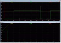
Here, the tempo of the protection (Not included the delays of the mosfets witch are 5µs+ 1µs of transition time to add.).
Red is the soft start : the full power is send in main PSU 1second after power on.
Green is the loudspeakers: Not connected at start, connected after 6 seconds.
To test the performance of the protection, i have send a pulse of 1.5V of 0.1ms duration at 20S !!!! it is the yellow signal. (the signal has been taken after the first stage, 1.5X4.7 = 7V)).It is the yellow trace.
The delay of reaction of the protection is.....10µs !!!!!!! Will be even faster with a higher signal.
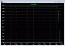
+6µs for the mos, it gives : < 16µs.
The loudspeaker stay disconnected when the problem had disappeared for 5 more seconds.
I think it can protect efficiently any loudspeaker and amp, against short circuit.
Well, i have one or two little things to modify before the final version, and it will be perfect. thank to your patience.
Red is the soft start : the full power is send in main PSU 1second after power on.
Green is the loudspeakers: Not connected at start, connected after 6 seconds.
To test the performance of the protection, i have send a pulse of 1.5V of 0.1ms duration at 20S !!!! it is the yellow signal. (the signal has been taken after the first stage, 1.5X4.7 = 7V)).It is the yellow trace.
The delay of reaction of the protection is.....10µs !!!!!!! Will be even faster with a higher signal.
+6µs for the mos, it gives : < 16µs.
The loudspeaker stay disconnected when the problem had disappeared for 5 more seconds.
I think it can protect efficiently any loudspeaker and amp, against short circuit.

Well, i have one or two little things to modify before the final version, and it will be perfect. thank to your patience.
Attachments
Last edited:
Hi Esperado 
Good scientific work performed here, I like it a lot, as I would watch R&D department of some production company, very insightful.
OK, protection looks to be universally suitable for any type of amp, fast and least invasive for the signal at both sides. What are my remarks for what can be added or improved I will list below and if you dislike, omit them completely.
Remarks:
- R18,R20 1k will half an input filter roll-off frequency since 1k/220p is usual low-pass filter values, so for an existing ready made amp remark to change or to replace input resistor with wire jumper should be made
- +12V trigger input should be over-voltage protected and CCS-ed, since preamp can in a case of failure (if this is the protection circuit intended to be without compromise/surprise) send live mains to the protection GND
- for power-up you should provide two steps, first: main power-on switch on the back side, to completely decouple amp from mains (second relay control), second: standby/on pushbutton with LED on the front panel
- second programmable (1-3s) delay ON +12V signal usually needed for the ready made amps to turn on some specific part of electronics, displays etc.
- temperature sensor with two level (50°C/75°C) comparator for low/high speed fan opearation
- 90°C overheating protection mode
Hopefully the remarks will be implemented, since protection/power-on functions should be a part of the same one circuit.
Regards, L.C.

Good scientific work performed here, I like it a lot, as I would watch R&D department of some production company, very insightful.

OK, protection looks to be universally suitable for any type of amp, fast and least invasive for the signal at both sides. What are my remarks for what can be added or improved I will list below and if you dislike, omit them completely.
Remarks:
- R18,R20 1k will half an input filter roll-off frequency since 1k/220p is usual low-pass filter values, so for an existing ready made amp remark to change or to replace input resistor with wire jumper should be made
- +12V trigger input should be over-voltage protected and CCS-ed, since preamp can in a case of failure (if this is the protection circuit intended to be without compromise/surprise) send live mains to the protection GND
- for power-up you should provide two steps, first: main power-on switch on the back side, to completely decouple amp from mains (second relay control), second: standby/on pushbutton with LED on the front panel
- second programmable (1-3s) delay ON +12V signal usually needed for the ready made amps to turn on some specific part of electronics, displays etc.
- temperature sensor with two level (50°C/75°C) comparator for low/high speed fan opearation
- 90°C overheating protection mode
Hopefully the remarks will be implemented, since protection/power-on functions should be a part of the same one circuit.
Regards, L.C.

(Thanks for your nice words, L.C. Nice to see-you here)- R18,R20 1k will half an input filter roll-off frequency since 1k/220p is usual low-pass filter values, so for an existing ready made amp remark to change or to replace input resistor with wire jumper should be made
Right. This bores me a little, but difficult to do better: I worried about adding a MOS in serial with the amp, and i can't rely on enough source impedance value in order to get the signal attenuated enough when the protection fire. I need-it in case of short circuit, to ensure there is no more signal in the output when the output MOS switch-off.
Clever, thanks.- +12V trigger input should be over-voltage protected and CCS-ed,
It is a 'building part', supposed to be that way in the final box, if any. But this circuit can be used inside an existing amp as well. Good suggestion, indeed.- for power-up you should provide two steps, first: main power-on switch on the back side, to completely decouple amp from mains (second relay control), second: standby/on pushbutton with LED on the front panel
Will not do-it. This stuff is complicated enough , and, if any external equipment has to be powered by this prot. remotely, i would prefer it is *before* the amp for current stabilized. Can be an other little board ?- second programmable (1-3s) delay ON +12V signal usually needed for the ready made amps to turn on some specific part of electronics, displays etc.
Any-way, we yet have a signal delayed of 1s. We can use it for this purpose ?
Only the last one was implemented. I believe not everybody have this need, as the amplifiers are supposed to have their own fan system, if needed, what do-you think ? Even this was to use the last 1/4 OPA in the delays parts, and to answer to the ask of a DIYer. It will fire the protection at 90° and relieve at 80°. Will think to that, if i have an idea how to make-it simple.- temperature sensor with two level (50°C/75°C) comparator for low/high speed fan operation
- 90°C overheating protection mode
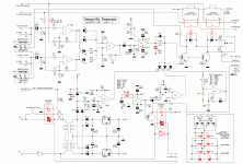
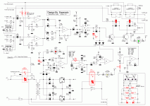
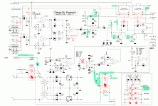
For coolet, the last (and hope least) version, including changes suggested by L.C.
In blue, the values you should check.
The transistor add been added to provide the choice to mount or not the indicating leds. If not there, the soft start would not work, because the leds where i serial.
In blue, the values you should check.
The transistor add been added to provide the choice to mount or not the indicating leds. If not there, the soft start would not work, because the leds where i serial.
Attachments
Last edited:
Member
Joined 2009
Paid Member
A cap will not protect your speakers, in case of oscillation, and often, if one output transistor goes in short circuit, the tweeter can die under this transient.
The boomer can be destroyed too, not burned, but hitting the back plate, can have his moving coil crushed, or some turn of the coil unglued.
The cap will not protect your amp against short-circuits on the speaker's lines.
The cap will not provide a soft and totally silent start/stop, Rolls Royce like.
And, most of all, with a very good amp, it sound very different with and without cap. Reason why most of the amplifiers have symmetrical rails nowadays.
- Home
- Amplifiers
- Solid State
- An ultimate amp protection circuit ?
