Thanks Carlo for pointing out this.
This is how people keep reinventing the wheel")
Isn't it Dyolf's #912 drawing and mine are almost identical?
The funny part is I'm not building right now this kind of tonearm but Micha Huber's Thales first tonearm. But still have work to do before listening some music on it...
This is how people keep reinventing the wheel
Isn't it Dyolf's #912 drawing and mine are almost identical?
The funny part is I'm not building right now this kind of tonearm but Micha Huber's Thales first tonearm. But still have work to do before listening some music on it...
Attachments
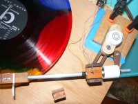
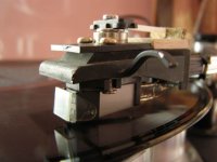
Carlo, you are right, I somehow missed some posts...I got this finished up last night and put it in the system with an AT95E at the business end.
It works. No stylus hunting, no skipping or mistracking.
There's more to do, but it has the crystalline quality I associate with LTs.
Attachments
Last edited:
The Bunny+two has been my daily player for the past week and I'm still very much enjoying what I'm hearing. With the Shure M91, it's especially good at rhythm and percussion.
It is a bit fiddly. Getting the best upright angle with the adjustable base takes time. To move the arm toward the record, you have to let the motion of the arm guide your hand instead of the other way around. Your hand just holds the arm up.
I put a single layer of electrical tape around the rims of both pulleys, which mostly eliminated slippage. I think slip could be totally ended with a small pin through the belt into each pulley. I need to take the arm back to my bench for a couple of things and I'll experiment with belt locks then.
This arm isn't difficult to build. It just takes care and patience.
Consty: When I saw your post, I thought "that looks familiar." I think your approach is better than mine, though, because you can get the measurements needed to build an accurate arm. Mine was an accident. I just happened to draw two control arms on the same drawing and a light went on. I wasn't able to open your files on my Mac, but I'll take care of that and I look forward to seeing them. Nice work and thanks for posting.
The Schroeder LT can be DIYed and has. If you detach the blue line then trace the point where it was connected as you move the arm keeping everything tangent on the other end, the trace is the shape you need for the magnet guide. After that think like a metal smith instead of a machinist to make the guide.
Carlo: Thanks for the forces analysis. I plan to go over them carefully. When I said the Bunny failed the string test, I meant it would not move in any direction when pulled. The belt prevents that. However, as the side force moves the arm inward, I believe SD starts to have an effect, but I don't know what the SD/SF proportion is at that instant.
The Bunny+two has a vertical eff mass of 6.2 gr. I also got 3 gr for the horizontal eff mass. I think Frank Schroeder said the belt helps with horizontal mass, but 3 gr is ridiculous and I don't know what to make of it. I'd like to make a larger, heavier Rabbit for low compliance cartridges.
Your active participation on this thread will be missed. Your contribution density (ideas/time) is very high. I hope this isn't a permanent Ciao.
Last edited:
Dear Doug, thanks for what you say; it is not a great merit, as retired there is even too much time to waste.
Some more words - when I started reading this thread, I thought there were many great theories and many very interesting and creative solutions, but too few checks (how many real and working arms posted?).
This could be done by a diyer: verify. In 10 years I tried many types of arms, vaguely understanding what is important and what's not. And why a diyer can make a good arm. but not an outstanding one: we make prototypes, sometimes well done, but that is only the starting point of a serious builder. All the work of progressive development (dozens of prototypes, tests, measurements, analyzes) that is - or should be - the industrial practice is lacking. But we diyers have a big advantage: to speak publicly about faults rather than merits, looking toghether for solutions instead of useless approval. There is no advantage in fooling ourselves or others.
Experiencing these arms and, above all, roughly measuring tracking forces, now I know directly the real obstacles to realize these kind of arms. This is the phase I consider ended, and to be leaved to people with more knowledge and able to master more sophisticated technologies.
I will continue to follow this fascinating challenge anyway.
ciao again - carlo
Consty: finding a good old round wheel is always less frustrating than "inventing" a square one, I can assure.
String test: found the same - that was surprising
Last edited:
Hi Doug
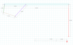
I'm really sorry you can't open my files on your Mac. Hoping you'll be able to, I'm posting also the measurements (in millimeters). I know it will look a little bit awkward and bulky but the longer the segments the better the tangential precision.
After I'll finish my current project (Huber's Thales "spider" arm), I'll probably delve into this design too (or maybe not, if the results will be so fascinating that will cut my DIY appetite in favor of listening to music, at least for a while...).
At the beginning of the 20th century, a very talented British writer, Jerome K. Jerome wrote: "When you have a bicycle, you either repair it or ride it. You'd never be able to do both.".
@Carlo: Totally agree on the square wheel
Attachments
Hi members! I haven't been following the thread closely so I'm sure I missed some recent posts. So happy to see Consty's new geometry, which is a variation of Doug's arm. I hope the GIF picture helps to see the geometry in motion. Also want to thank Carlo's contribution to this thread with his tonearms and drawings and practical thoughts. We will miss your inventions!

.
.
Last edited:
DD
Do you agree with nocdplz that this is a thread for theory not nuts & bolts practical applications? That would be all I could offer, my unoriginal derivative attempt to make something work without the math to show why it works. Hopefully. You know, for fun. Giggles and whatever. I'm just a tradesman, retired.
Thanks for starting all this.
Hi all,
For those who can install Algodoo, I have also made a version of my geometry in this 2D physics simulation application and attached the simulation here. I used the laser to trace the reflection in the spindle so this is the most accurate (and unforgiving) simulation. Enjoy!
For those who can install Algodoo, I have also made a version of my geometry in this 2D physics simulation application and attached the simulation here. I used the laser to trace the reflection in the spindle so this is the most accurate (and unforgiving) simulation. Enjoy!
Attachments
Hi all,
For those who can install Algodoo, I have also made a version of my geometry in this 2D physics simulation application and attached the simulation here. I used the laser to trace the reflection in the spindle so this is the most accurate (and unforgiving) simulation. Enjoy!
Outer groove error looks pretty big, have you measured?
It appears the error is due to the laser reflection coming from perimeter of the spindle instead of the center of the spindle, which should be a single point. By aiming the laser at the spindle's small circle, the reflection can only be tangent at one spot on the groove.
I downloaded the Algodoo app, which is pretty cool and playful. Unfortunately I don't know how to convert the PHZ file into other video files such as MP4 or GIF so people can see the movement and laser reflection. Some screen grabs below.


I downloaded the Algodoo app, which is pretty cool and playful. Unfortunately I don't know how to convert the PHZ file into other video files such as MP4 or GIF so people can see the movement and laser reflection. Some screen grabs below.
Last edited:
Dear 2wice: "Outer groove error looks pretty big"
Guilty as charged. I never claimed my geometry is perfect. This is why, being honest and in pursuit of truth, I didn't stop at the linkage2 simulation which might look better than it really was.
Anyway, just for comparison, I've just made anther simulation modeling a traditional pivoted tonearm with overhang and offset angle (attached). Mine is better
Dear directdriver: "It appears the error is due to the laser reflection coming from perimeter of the spindle instead of the center of the spindle"
Unfortunately, mirrors don't lie. No matter the diameter of the cylinder a ray is thrown at, as long as it is pointed to the center, the ray will return right back to the source. If I made the spindle disc smaller, the ray would have missed it altogether at large miss-angling, but the error would have remained the same.
Guilty as charged. I never claimed my geometry is perfect. This is why, being honest and in pursuit of truth, I didn't stop at the linkage2 simulation which might look better than it really was.
Anyway, just for comparison, I've just made anther simulation modeling a traditional pivoted tonearm with overhang and offset angle (attached). Mine is better
Dear directdriver: "It appears the error is due to the laser reflection coming from perimeter of the spindle instead of the center of the spindle"
Unfortunately, mirrors don't lie. No matter the diameter of the cylinder a ray is thrown at, as long as it is pointed to the center, the ray will return right back to the source
. If I made the spindle disc smaller, the ray would have missed it altogether at large miss-angling, but the error would have remained the same.Attachments
No matter the diameter of the cylinder a ray is thrown at, as long as it is pointed to the center, the ray will return right back to the source
You are absolutely right. Duh! Brain fart...

Dears,
I really wanted to explore the full potential of this geometry and this is why I carefully plotted the links at 0.2 millimeter precision level (the best Algodoo permits).
It works much better than my first Algodoo attempt and most probably than my initial linkage2 simulation.
I am sure a member here more math savvy than me can calculate the exact locus and therefore the exact lengths and angles of this four bar mechanism for the ideal path.
But even so the simulation attached here seems really promising.
My math skills are limited to counting to one hundred: 0, 1, 10, 11, 100
Attachments
post scriptum
I thought back to my first post on this thread (#1128 - double tracker): couldn't leave the PLT world without trying this too. A silly, provocative idea ... but, strangely, it works.
Smooth tracking, no stylus bending, no skipping, geometry ok: a tangent solution really "skating free" (or not?). No need of strange tonearms, no need of tracking forces used for guiding: halved side force, some more stylus drag (because of 50% more VTF needed) but perfectly aligned.
But the sound?
Seems all ok at first but, hearing carefully, the upper octaves are very dirty, especially in "pieno" (full - how is said?) orchestral passages. For sure resonances from the guiding stylus and chattering of the bearing .
Problems very difficult to be corrected: in my experience a bearing just over of the stylus is one of the worst thing to deal with (to be left to swiss watchmakers). Resonances could be damped just with multiple decoupling and just a cartridge builder could face it properly, since the system is really complex to investigate.
So it seems another dead end track, but maybe no more than others for someone really skilled in micro machining.
carlo
Attachments
Last edited:
Rotary
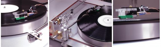
Hi, Carlo. Interesting device. I've tried rotary shell just to hear if it makes difference in sound (and in my case it didn't). I used good quality computer hard drive bearing, and flat plastic spring (on the top) for centering stylus. Actually, shell itself doesn't rotate, turns the small platform inside it, together with the cartridge.My next idea was to use this rotary shell for the same purpose, as you do, but with small brush instead of the second stylus. Of course, without centering spring. Maybe, now I'll try it.
I see, you used headphone wires? I did for some of my DIY arms, because flexibility exceeds most of usual tone arm wires ...
Sorry for dusty pics
Attachments
Last edited:
Not having the right materials I've made a quick proto with lexan and a simple ball bearing.
More than in the bearing, problems are in decoupling: there are two styli, and the guiding one influences the reading one. We must consider the relationship between the compliance and the VTF of each one, an infinity of variables. Cables are made with the wire of a micro transformer, it is essential that they are very flexible.
Maybe a brush can not track with the necessary precision, here the outer blank grooves make the two styli work in the same groove.
good luck Walter, let us know
carlo
off topic (almost)
Hi all.
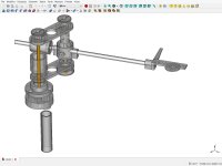
A friend diyer made me curious about 3d printing, so I was forced to put my hands for the very first time in 3d CAD design. After the downloading of a free dumb-proof program, here are some results.
Now I have to understand if these pieces are correctly printable (having good results is less simple than what we think - thickness, shrinks, overhangs, etc) but the idea of making a tonearm arm reproducible by any lazy diyer (simply going to a 3d service and assembling the parts) seems amusing. Probably the easiest way of seeing a real PLT in action: the Rabbit, built in a traditional way, deserve to be heard.
Any advice is welcome: when verified (with your, and my friend, aid), I'll try to get it printed, and if it will work properly I'll post the files of parts - If someone is interested, of course
carlo
I'm thinking too about a sort of 3D printable Bunny (but maybe more a Doug's Double Pivot) without bearings and pulleys - I'll let you know
Hi all.
A friend diyer made me curious about 3d printing, so I was forced to put my hands for the very first time in 3d CAD design. After the downloading of a free dumb-proof program, here are some results.
Now I have to understand if these pieces are correctly printable (having good results is less simple than what we think - thickness, shrinks, overhangs, etc) but the idea of making a tonearm arm reproducible by any lazy diyer (simply going to a 3d service and assembling the parts) seems amusing. Probably the easiest way of seeing a real PLT in action: the Rabbit, built in a traditional way, deserve to be heard.
Any advice is welcome: when verified (with your, and my friend, aid), I'll try to get it printed, and if it will work properly I'll post the files of parts - If someone is interested, of course
carlo
I'm thinking too about a sort of 3D printable Bunny (but maybe more a Doug's Double Pivot) without bearings and pulleys - I'll let you know
Attachments
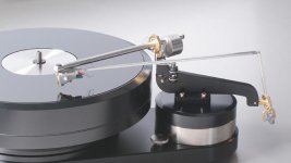
I have been trying to see one of these in action. But even dealers who carry Schroder arms say, "We deal in 'real' Schroeder arms, the LT is made by Steve Dobbins." Is that really so? Not that it really matters...
What I really wanted to see was what happens to the magnet / magnet guide proximity if the arm is yanked quickly? I presume the magnet loses track of the guide and later need to be re-aligned. The newer pictures show a different arrangment that may not allow such separation.
I would appreciate any enlightenment on this matter.
Do the magnets ever decouple?
I have been trying to see one of these in action because I wanted to see what happens to the magnet / magnet guide relationship if the arm is “yanked away” such that the magnets separate? I presume once the magnet decouples from the guide, it later needs to be brought closer, to get back in alignment. The newer pictures show a different arrangment that may not allow such separation.
(As I said, I have been trying to see one of these in action. But even dealers who carry Schroder arms say, "We deal in 'real' Schroeder arms, the LT is made by Steve Dobbins." Is that so? Not that it really matters...)
I would appreciate any enlightenment on this matter.
Hi guys,
Just a few remarks..
(...)
The (sorry, my) LT arm does not follow the Thales guide circle. Not just for the impossibility to achieve "perfect" tangency across the record, but mainly because the end of the guide bar isn't rigidly connected to the guide rail(magnetic coupling...) , the angle between both elements changing over the radius of the record. That alone needs to be compensated for...
The bearings in the LT arm do not allow for any slop, only the magnetic coupling does, - and for good reasons. Among those the near elimination of the fundamental arm-cartridge resonance peak in the lateral plane.
A peaceful and happy holiday season to all!
Frank
I have been trying to see one of these in action because I wanted to see what happens to the magnet / magnet guide relationship if the arm is “yanked away” such that the magnets separate? I presume once the magnet decouples from the guide, it later needs to be brought closer, to get back in alignment. The newer pictures show a different arrangment that may not allow such separation.
(As I said, I have been trying to see one of these in action. But even dealers who carry Schroder arms say, "We deal in 'real' Schroeder arms, the LT is made by Steve Dobbins." Is that so? Not that it really matters...)
I would appreciate any enlightenment on this matter.
- Home
- Source & Line
- Analogue Source
- Angling for 90° - tangential pivot tonearms