I recently bought this push button " Anodized Aluminum Push Button with Red Light Circle 1NO1NC 250V 5A Ø19mm Black " from Audiophonics
https://www.audiophonics.fr/en/push-button/anodized-aluminum-push-button-with-red-light-circle-1no1nc-250v-5a-o19mm-black-p-8797.html
There are 6 pins and I don't know how to connect them in order for the LED to be switched on , when is powered and off when its not. Till now the LED remains on all the time.
I use the push button as a power button and I want to know when my system is on/off based on the LED. I am trying to connect directly the AC cables to the LED and then to the transformer.
Do you have any idea ?
Attachments
My understanding is that with this switch you can't do what you want since the LED is rated for 12V and if you connect it to AC mains then it will explode or even worse may occur.
Please be careful that you can't mess around with 220V electricity!
Indeed, I think you need something like this switch https://www.aliexpress.us/item/3256802783708106.html with the LED rated for 220V.
Of course you can however use your actual switch in other projects by connecting the LED to a maximum voltage of 12V from a different circuit.
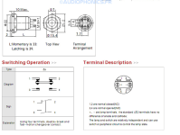
@ulogon Thanks a lot for your reply ! I think that the LED is for up to 250V ( aluminium Black & Light Circle Red 1NO1NC 250V 5A Ø19mm ) so I think that is fine. The problem is with the pins . Do you have any schematic for the six pins configuration ? Please have a look at the figure that I uploaded as well if you have time.
No problem.
Can you please read on the body of your switch what voltage value is there?
From the picture you posted it looks like it's 12V.
However, assuming it is 220V I still believe that the switch is not suitable for the purpose just because the notes you posted say switch and the LED are "relatively" independent.
Anyway, if you have a tester or a battery you can check what happens on the + or - pins when you press and/or release the button.
Then if confirmed it should be easy.
No. The switch is rated 250v.I think that the LED is for up to 250V
It says "12v diode". That is the LED, the only diode.
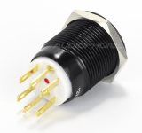
Indeed I have a few of these straight from AliExpress. Momentary and latched. The voltage on the side is for the LED indicator. I also found it had to swap the wires over in the connector for the LED from the 'top 2' to the bottom 2. Pending orientation when viewed obviously.
Edit I...can see your pins are maybe different to mine.
Edit I...can see your pins are maybe different to mine.
The problem with this kind of issue is that 1) There are many variants that look similar but differ in details 2) Datasheets provided by the seller is not always the correct one.
I was about to type a long reply covering various possibilities but it will be better if the OP could provide a photo of the pin side that's clear enough to show the pin markings.
I was about to type a long reply covering various possibilities but it will be better if the OP could provide a photo of the pin side that's clear enough to show the pin markings.
The drawing shows the LED terminals as screws whereas the image shows them as solder lugs. There could be other differences. The description says that the switch is a monostable. I take this to mean that it's a momentary contact type. Don't know if this is correct or if it's what the OP wants.
No, they are not screws; they are pins, the negative and positive. I don't understand the wiring. This is a power button, so I don't understand the wiring from the plug—push button with LED—transformer. The problem is that I did something wrong, and the LED switch does not turn off.
You don't seem to follow any leads and you stick to your opinions and that's why we don't proceed.the LED switch does not turn off.
You don't want to realize that your switch has the LED that isn't subservient to the button: that's, it's always ON.
I suggested a tester or battery and you didn't.
However, IF your switch is exactly the one in the drawing you attached, the wiring is easy:
break a wire from mains and attach one of the two ends (better the one with the phase, if any) to pin 3 and the other to pin 4.
That will only serve to turn on or off anything that comes after the socket you have in the wall.
The LED on and off most likely is not linked to the button.
But in the switch I linked to you earlier it is.
")
You have already attached the LED and it will not turn off just because your switch is not designed to do so.
I guess it's designed to turn on an LED that's plugged into some circuit where it will turn on or off, but it's not controlled by your switch button.
Disclaimer: I take no responsibility for what you will do since you haven't provided enough information to consider them valid and I simply used the drawing you provided and we don't know if it's accurate.
All right. Going strictly by the information provided by the OP and the seller's data, this should work.
The resistor value is based on a 240V system since the link was to a European site. The LED will not be very bright but enough for ON/OFF indication.
The resistor value is based on a 240V system since the link was to a European site. The LED will not be very bright but enough for ON/OFF indication.
Last edited:
I didn't get it from somewhere. I drew it after working out a practical circuit in my head.
There are other possibilities if we knew more about what the OP is trying to do.
As to whether it will work correctly, that depends on whether the (limited) information provided by the OP is correct. If it is, there's no doubt that it will work.
There are other possibilities if we knew more about what the OP is trying to do.
As to whether it will work correctly, that depends on whether the (limited) information provided by the OP is correct. If it is, there's no doubt that it will work.
There are two main failure modes for diodes and resistors. They either go open or short. If either one fails open, the LED will stop lighting up, nothing else. If the resistor shorts (which is very rare), both the diode and the LED will go pop. If the diode shorts, both the the resistor and the LED will overheat and die, but not immediately.Interesting, but even assuming that it will work (just as I hope for the OP) I sincerely wonder what happens if the diode 1N4007 (or even the resistor) under 240VAC fails.
BTW, I've been designing electronic circuits since the late 1960s. There were no ICs or microprocessors then. Everything had to be designed with transistors, vacuum tubes, resistors, capacitors, etc.
I drew the diagram in a way that a novice - which the OP obviously is - could follow it.
Last edited:
- Home
- Design & Build
- Construction Tips
- Anodized aluminium push button with LED